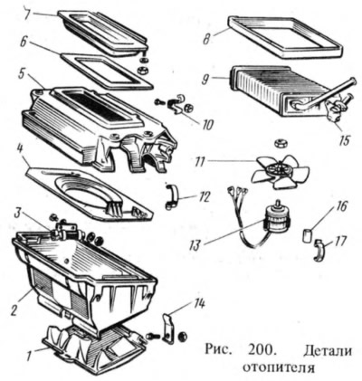
The casing 2 of the fan is attached to the radiator casing with four spring clips 12. A guide casing 4 of the fan is installed between the casings 5 and 2. In the center of the fan casing, with the help of two spring brackets and pillows 16, an electric motor 13 with a fan 11 is installed. An additional resistor 3 is attached to the left side of the casing, connecting and disconnecting it ensures low and high rotation speeds of the electric fan.
An air duct is installed along the front wall of the radiator casing 5, through which the air from the electric fan rises up to two deflectors 6 (see fig. 198). Deflectors direct air onto the windshield or directly onto passengers. At the bottom of the casing 2 (see fig. 200) on the brackets 14, an air distribution cover 1 is installed, when opened, the air is directed to the feet of the passengers. At the same time, the amount of air to the deflectors is reduced. The tightness of the heater is ensured by gasket 6.
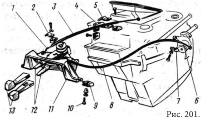
The heater is controlled by turning on the electric fan, deflectors, air distribution cover 1 and two handles 13 (pic. 201) on the instrument panel. The handles are mounted on the levers 12 of the bracket 11. The levers are connected by flexible rods 1 and 6 to the levers of the air intake cover and the heater tap. Shells and rods are clamped with spring clips 2, 5 and 7, and clip 5 is mounted on bracket 4. Bracket 11 is attached to the instrument panel with bracket nuts 9 and screws 10.

The top handle regulates the amount of fresh air entering the heater, and the bottom handle regulates the amount of fluid entering the radiator. Colored symbols show the position of the handles.
Vehicles 21011 and 21013 additionally have exhaust ventilation on the roof side panels. The air is sucked out through the slot under the upholstery of the side panel, squeezes out the rubber valve and exits through the decorative grille. The damper prevents outside air from entering in crosswinds.
