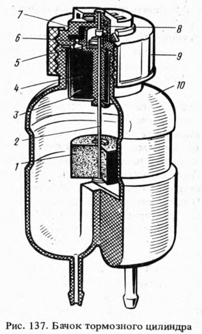
The body of the tank is made of translucent plastic, which allows you to control the liquid level visually.
A cap 9 is screwed onto the filler neck of the tank, which presses the body 7 of the terminal device and the reflector 3 to the end of the neck. In case 4, a device for monitoring the level of liquid in the tank is mounted. It consists of a float 1, on the rod 2 of which there is a movable contact 6, and a fixed contact 5 fixed in a plastic housing 4.
When the liquid level drops, the float drops, the contacts close the circuit of the control lamp, which lights up with a constant light.
A pusher 8 is installed in the central hole of the housing 7 of the terminal device, when pressed, the operability of the control lamp circuit is checked at a full liquid level in the tank. In case 7 there are two terminals for connecting wires to them.
