Open large image in new tab »
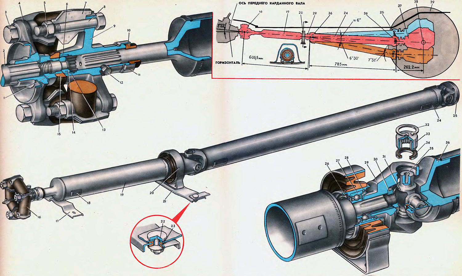
1. Nut of the rear end of the driven shaft of the gearbox. 2. The driven shaft of the gearbox. 3. Bolt. 4. Flange of the driven shaft of the gearbox. 5. Nut. 6. Bushing centering the flange of the front propeller shaft. 7. Flexible coupling insert. 8. Bolt. 9. Front propeller shaft flange. 10. Front shaft flange seal. 11. Gland clip. 12. Plug holes for lubrication of splines. 13. Retaining ring. 14. Centering ring. 15. Centering ring seal. 16. Elastic coupling. 17. Safety bracket. 18. Balancing plate. 19. Front propeller shaft. 20. Intermediate support. 21. Crossbar of the intermediate support. 22. Distance sleeve. 23. Rubber bushing. 24. Rear driveshaft. 25. Flanged fork of the cardan shaft. 26. Dirt deflector. 27. Bearing of an intermediate support. 28. Retaining ring. 29. Front propeller shaft fork. 30. Nut for the front propeller shaft. 31. Cross of the cardan shaft. 32. Retaining ring. 33. The bearing of the cross of the cardan shaft. 34. An epiploon of a crosspiece of a cardan shaft. 35. Grease socket. 36. Fork rear driveshaft. 37. Rear axle gearbox. 38. Wheel axle. 39. The driving wheel of the car.
The cardan gear is used to transmit torque from the driven shaft of the gearbox to the drive shaft of the final drive. And since the relative position of the rear axle, in which the main gear is mounted, and the gearbox changes with changes in load and with shocks while driving, the transmission of torque must be carried out at a changing angle. Cardan shafts allow you to transfer torque from the gearbox to the rear axle, despite its fluctuations.
The cardan gear includes two tubular shafts, two cardan joints with needle bearings, an intermediate support, a splined flange and an elastic coupling.

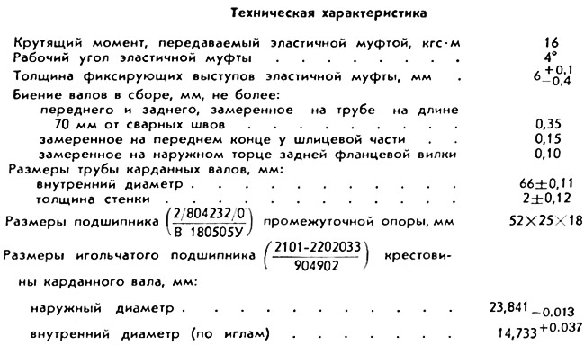
Front 19 and rear 24 cardan shafts are made of thin-walled steel tube with an inner diameter of 66 mm. Two identical forks 36 are pressed into each end of the rear propeller shaft and welded. Bearings 33 of the cross are pressed into the holes of the eyes of the forks 36, which are kept from falling out by spring retaining rings. Each cardan bearing has 22 needles with a difference in needle diameters in one bearing not more than 0.004 mm.
Between the ends of the cross and the bottoms of the needle bearing housings, an axial clearance is set in the range of 0.01-0.04 mm, as a result of which the cross is centered in the forks and cannot move along the axes of the trunnions.
The necessary axial clearance at the crosspiece is provided by the selection of retaining rings 32, manufactured in different thicknesses and colors. The color of the ring depends on its thickness: the 1.50 mm thick ring is natural, 1.53 is dark brown, 1.56 is blue, 1.59 is black and 1.62 is yellow.
When assembling cardan parts, a 1.56 mm thick ring is installed in the groove of one of the eyes and, when the second bearing is pressed in (in this case, the cross rests against the bottoms and there is no gap), measure the distance between the end of the second groove and the bottom of the bearing with a probe. And if this distance is, for example, 1.56 mm, then to ensure the necessary axial clearance, a ring with a thickness of 1.53 mm should be installed. If this distance is less than 1.53 mm, then the first ring should be replaced with a 1.50 mm thick ring. If the measured distance is more than 1.62 mm, then the originally supplied 1.56 mm thick ring should be replaced with a 1.62 mm ring.
After installing the retaining rings, hit the bearing with a plastic-headed hammer. Under the action of impact and elastically compressed rubber seals, the gap between the bottom of the bearing and the retaining ring will be selected and gaps will appear between the ends of the spikes of the cross and the bottoms of the bearing housings.
When disassembling the cardan, marks should be made on the parts by which it would be possible to determine their previous position if the assembly is carried out without replacing parts. Retaining rings of different thicknesses must also not be interchanged. To lubricate the needle bearings of the cardan during assembly, lubricate the inner surface of the housing with LITOL-24 grease (0.4—0.6 g per bearing) and fill the cavities 35 in the spikes of the cross.
To retain grease in the needle bearings and prevent dirt and water from entering them, rubber seals are installed on the spikes of the cross in stamped steel cages. The seal of the needle bearings of the cross is provided by an interference fit between the end face of the bearing housing and the rubber ring of the stuffing box.
Splined tips are pressed into the tube of the front driveshaft and welded. A flange slides on the splines of the front tip, connecting the driven shaft of the gearbox and the driveline through an elastic coupling. The flange, and with it the entire front shaft with an elastic coupling, is centered on the ring 14, mounted on the driven shaft of the gearbox.
The front cardan shaft can move in the slots of the flange 9, thereby changing its length. Shortening or lengthening the shaft is necessary because the distance between the gearbox and the rear axle does not remain constant when the suspension of a moving vehicle oscillates. To keep the lubricant in the spline connection and to protect it from contamination, a rubber seal 10 is installed in the steel cage 11 at the rear end of the flange 9, and a rubber sealing ring is installed in front, at the end of the driven shaft of the gearbox. The spline connection is lubricated through a hole closed with a plug 12.
The rear tip of the front propeller shaft passes through the ball bearing of the elastic intermediate support 20. The elastic rubber pad of the support absorbs the vibration of the propeller shaft and allows axial movement of the front propeller shaft. The ball radial bearing of the intermediate support is a sealed bearing with seals and LITOL-24 grease applied during assembly. For additional protection, mud deflectors 26 are installed on both sides of the bearing. From axial movements, the outer ring of the bearing is held on one side by the shoulder of the housing, and on the other, by a snap ring 28 installed in the groove of the housing. The final processing of the hole for the bearing in the housing is carried out after the rubber cushion with the housing and the propeller shaft support bracket has been vulcanized.
The bracket for the intermediate support of the cardan shaft is attached to the cross member with two bolts and nuts, and the cross member is fastened with nuts to two welded bolts on the floor of the body with the installation of steel spacer bushings 22 and rubber insulating bushings 23.
On the splines of the rear tip of the front cardan shaft, a fork 29 of the cardan joint is installed and secured with a nut 30. Between the end of the fork 29 and the protrusion of the rear tip, the inner ring of the bearing 27 of the intermediate support and the mud deflectors 26 are clamped.
The driven shaft of the gearbox is connected to the driveline with an elastic flexible coupling 16, which reduces noise and vibration and allows the transmission of torque at an angle. Elastic coupling consists of six round rubber elements with rigid metal inserts placed between them with holes for fastening bolts.
The insert of the flexible coupling is a reinforcement welded from two stamped halves with a hole ∅ 12+0,25+0,1 for the fastening bolt and a protrusion that enters the groove on the connecting flanges when installing the coupling.
The elastic coupling is centered on the flange 4 of the driven shaft of the gearbox with the protrusions of three inserts and three bolts 3 with nuts is attached to it. The other three bushings serve to center and fasten the coupling to flange 9 of the front propeller shaft. The protrusions of the liners, included in the grooves of the flanges, in addition, fix the liners when tightening the nuts of the bolts of the flexible coupling to the flanges.
The coupling in the assembled unit, as well as during transportation and storage, is in a pre-compressed state of the rubber elements. During transportation and storage, a bandage made of steel tape with a special lock is used.
In the assembled unit, the fastening bolts of the elastic coupling are located on a circle of ∅ 100 mm, while in the free state of the coupling, the holes for fastening in the liners are located on a circle of ∅ 110 mm. The ratio of the length and thickness of the straight rubber elements of the clutch is chosen so that each of them works as a beam, hooked at the ends and loaded in the longitudinal direction.
The driveline is connected to the drive gear of the rear axle reduction gear by means of a flange yoke 25, the lugs of which include two bearings of the rear universal joint. The flange yoke is attached with four special bolts with nylon insert self-locking nuts to the flange of the rear axle drive gear.
A safety bracket 17 is installed under the front propeller shaft, which prevents the shaft from falling when the car is moving in case of destruction of the hinge.
During manufacture, the cardan assembly is subjected to dynamic balancing on special machines. The imbalance is eliminated by welding balancing plates 18 at the ends of the pipes. Unbalance is allowed no more than 22 gs cm. In this regard, when disassembling the transmission, it is necessary to mark the relative position of the parts to be separated so that they can be installed in their original position during assembly. Violation of this condition will lead to an imbalance in the transmission, which will cause vibrations that destroy the transmission and the vehicle body. If the pipe is bent as a result of the impact and the gear cannot be dynamically balanced, the bent shaft must be replaced.
