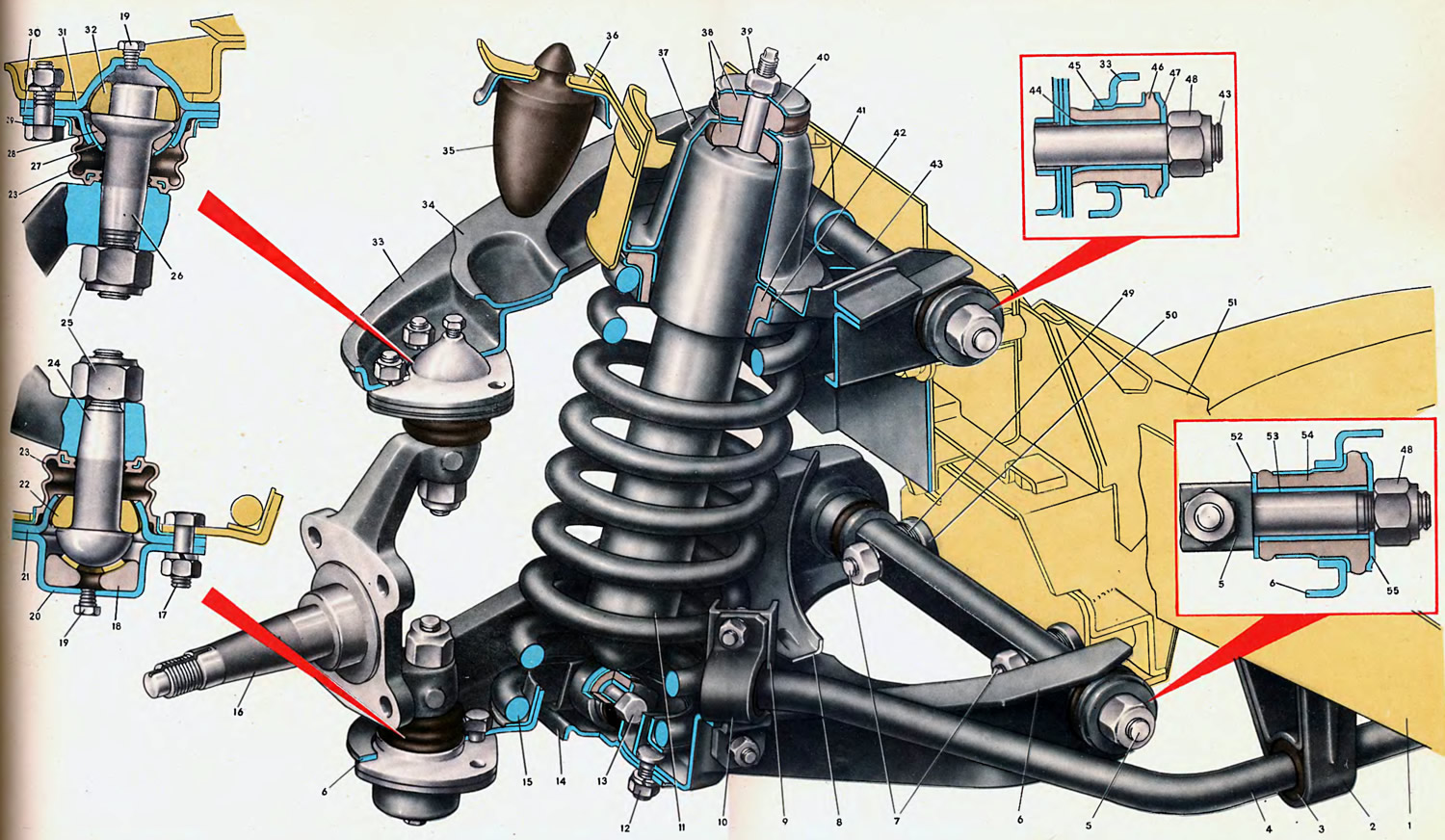
The suspension consists of a guide device, elastic elements and shock absorbers.
The suspension guiding device determines the movement of the wheels relative to the body, and also transfers forces and moments from the wheel to the body. The main elements of the guide device are the upper and lower levers and the knuckle pivotally connected to them.

Open large image in new tab »
1. Spar. 2. Stabilizer bracket. 3. Rubber cushion. 4. Stabilizer bar. 5. The axis of the lower arm. 6. Lower suspension arm. 7. Hairpin. 8. Amplifier of the lower arm. 9. Stabilizer bracket. 10. Stabilizer clamp. 11. Shock absorber. 12. Bracket bolt. 13. Shock absorber bolt. 14. Shock absorber bracket. 15. Suspension spring. 16. Swivel fist. 17. Ball joint bolt. 18. Elastic liner. 19. Cork. 20. Insert holder. 21. Bearing housing. 22. Ball bearing. 23. Protective cover. 24. Lower ball pin. 25. Self-locking nut. 26. Finger. 27. Spherical washer. 28. Elastic liner. 29. Clamping ring. 30. Insert holder. 31. Bearing housing. 32. Bearing. 33. Upper suspension arm. 34. Amplifier of the upper arm. 35. Buffer compression stroke. 36. Bracket buffer. 37: Support cap. 38. Rubber pad. 39. Nut. 40. Belleville washer. 41. Rubber gasket. 42. Spring support cup. 43. The axis of the upper arm. 44. Inner bushing of the hinge. 45. Outer bushing of the hinge. 46. Rubber bushing of the hinge. 47. Thrust washer. 48. Self-locking nut. 49. Adjusting washer 0.5 mm 50. Distance washer 3 mm. 51. Crossbar. 52. Inner washer. 53. Inner sleeve. 54. Rubber bushing. 55. External thrust washer.
The top 33 and bottom 6 arms are shaped fork parts stamped from 3.5 gauge mild steel (for upper) and 3.0 mm (for the bottom). Stamped amplifiers 34 and 8, welded to the levers 33 and 6, increase their rigidity.
Bracket 9 for attaching stabilizer 4 is welded to the front collar of lever 6 in its middle part.
Hinges 45 are pressed into both eyes of the lever 33 on rubber bushings 46 made of highly elastic rubber.
Note: When replacing hinges, a pressing force of at least 500 kgf will be required. When pressing in new hinges, the distance between their inner ends must be kept within 146.6 + 1 mm.
Hinges on rubber bushings 54 are also pressed into the eyes of the lever 6. The hinges are mounted on the necks of the axle 5 with a gap of 0.02-0.25 mm. At both ends, the hinges are clamped with thrust washers, which are pulled together by a self-locking (with nylon insert) nut 48, screwed up to the stop on the threaded end of the axle 5. The final tightening of nuts 48 with a torque of 10 kgf·m is carried out under a static vehicle load of 320 kg.
The steering knuckle 16, pivotally connected to the front suspension arms, is a critical part on which the wheel hub with bearings, the front brake caliper with the mounting bracket, the brake guard and the swing arm are installed.
Articulated ~ connection of the steering knuckle with the levers is carried out by ball bearings, which are hinges of an integral design with sufficient mobility, allowing the suspension elements to move in a horizontal (to turn) and vertical (vibrations from rough road) planes within the calculated limits.
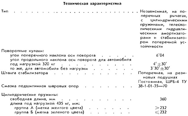
The total angle of deviation of the ball pin relative to the support body is possible: at the upper ball joint up to 55°, at the lower ball joint up to 45°.
Ball pins 24 and 26 with their heads are enclosed in housings welded from stamped halves. The heads of the ball pins are composite and are equipped with hemispherical bearings 22. From below, the ball pins are pressed with elastic inserts 28 and 18 made of oil-resistant rubber. Moreover, the liner 28 rests against the spherical steel washer 27, which slides along the yoke 30 when the suspension oscillates, and the liner 18 is motionless and has a vulcanized layer of a mixture of nylon with molybdenum sulfide on the friction surface with the ball head of the pin 24.
Before welding, a sealant is applied to the connectors of the bearing housings of the ball bearings and then the halves under a certain tightness, due to the compression of the elastic rubber liners 18 and 28, are welded at three points.
After welding, the bodies of the ball bearings are filled with ShRB-4 grease through the holes closed with plugs 19.
The pins of the ball bearings in the areas of contact with the bearings are zinc-plated and hardened to high hardness. Ball pin bearings are ceramic-metal, wear-resistant. The bearing housings 21 and 31, as well as the cage 30, are also cyanided and hardened along the friction surfaces to high hardness to increase wear resistance.
The friction surfaces of the ball bearings are reliably protected from the ingress of abrasive particles and moisture by protective covers 23, which are corrugated pipes made of chloroprene rubber. A mating steel flange is vulcanized from the wide end of the branch pipe, and a steel ring is inserted into the shoulder of the other end, which reinforces the edge and increases the reliability of sealing the protective cover with the pin.
Before installing the protective covers on the supports, SHRB-4 grease is placed inside for 50-70% of the cover volume.
Mounting levers to the body. The upper arm through the hinges is attached to the front end using the axle 43, under the hexagonal head of which on one side and the nut 48 on the other side there are thrust washers 47 covering the ends of the rubber bushings.
The lower lever with its axis 5 is mounted on the cross member 51 of the front suspension on two studs 7. When installed on the studs, distance washers 50 3 mm thick and packages of shim washers 49 0.5 mm thick each are placed on the studs between the mating plane of the cross member and the axis of the lever. These washers are needed to adjust the wheel alignment angles. The tightening torque of the fastening nuts is 8 kgf·m.
The suspension travel when moving the wheel up is limited by the buffer 35, when moving down - by the shock absorber 11.
Maximum suspension travel under load: up 90 mm; down 65.5 mm (VAZ-2101), 68 mm (VAZ-2102), 73.5 mm (VAZ-2103).
The elastic element of the suspension is a coil spring 15. In the suspension, the spring is installed in the thrust between the lower arm 6 and the upper support 37 with a pre-compression of about 300 kgf. Between the circular shoulder of the support and the spring, a rubber insulating gasket 41 and a steel support cup 42 are installed.
Before installation on the car, the suspension springs are sorted by length under a control load of 435 kgf into two groups, which are marked with a yellow or green stripe applied on the outside of the middle coils. As a rule, springs of only one group should be installed on the front and rear suspensions of the car.
Anti-roll bar. The front suspension is equipped with a stabilizing device that increases the stability of the car when cornering and reduces body roll.
With an unequal load on the right or left suspension, the stabilizer bar begins to work as a torsion bar. Twisting, it transfers the overload from one suspension to another and thereby evens out the deformation of the springs.
The stabilizer is a rod 4, the knees of which are connected to the brackets 9 using clamps 10. A rubber shock-absorbing cushion 3 is put on the rod 4 under the clamp 10. The middle part of the rod is fixed to the car body using two composite brackets 2, between the inner pillar and the outer clamp pillow stuck 3.
The hydraulic shock absorber, designed to dampen vibrations of the body and wheels, is installed inside the spring 15. The upper end of the shock absorber is attached with a nut 39 to the cap 37. A rubber cushion 38 is placed between the cap and the shock absorber casing; the second pillow, pressed with disc washers 40, is installed on the shock absorber rod on top of the cap. This connection allows the shock absorber to deviate during suspension oscillations in both directions up to 5°.
On the shank of the shock absorber rod there are turnkey flats S = 5 mm to keep the rod from turning when screwing on the nut 39; nut tightening torque 1.5 kgf·m.
The lower end of the shock absorber with an eye is attached to the cheeks of the bracket 14 using a bolted connection 13; nut tightening torque 6 kgf·m.
Rubber suspension elements (lever pivots, lower lug hinge and shock absorber upper end mounting pads, spring insulating gasket, etc.) are also designed to dampen high-frequency oscillations and vibrations that occur when the car is moving.
