
Open large image in new tab »
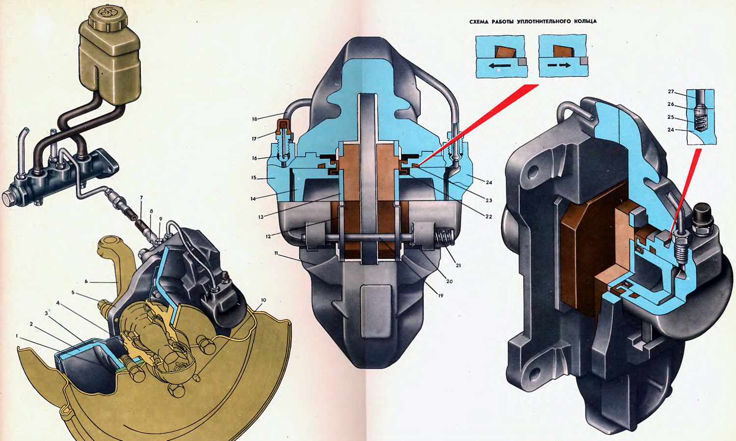
1. Disc clamping ring. 2. Brake disc. 3. Brake guard. 4. Wheel hub. 5. Caliper bracket. 6. Steering knuckle. 7. Flexible hose. 8. Guide bracket. 9. The union of fastening of a tip of a flexible hose. 10. Guide pin. 11. Front brake caliper. 12. Brake shoe spring. 13. Brake shoe assembly with lining. 14. Piston. 15. External brake cylinder. 16. Hose fitting for bleeding brakes 17. Protective cap of the fitting. 18. Connecting tube. 19. Brake shoe pin. 20. Finger pin. 21. Spacer spring. 22. Protective cuff. 23. O-ring. 24. Internal brake cylinder. 25. Detent spring. 26. Cylinder retainer. 27. The groove of the caliper under the latch.
The brake mechanism of the front brake is mounted on a bracket 5, fixed on the steering knuckle 6 with four bolts, the nuts of which are locked in pairs against self-unscrewing by lock washers. Simultaneously with the bracket on the steering knuckle, the stamped steel protective cover 3 of the brake and the rotary lever are fastened with the same bolts. The tightening torque of the fastening nuts is 6 kgf·m. The front brake caliper 11 is attached to the ears of the bracket 5 on its inner side with two hexagonal head screws. After tightening to a torque of 3.5 kgf·m, the screw heads are locked with lock washers, the petals of which are bent on the verge of the caliper and the screw heads.
The caliper is the base part for installing hydraulic brake cylinders and brake pads and is a complex casting of ductile iron. A radius groove is made in the center of the caliper to cover the brake disc 2. On the side walls of the radius groove, two transverse grooves are made for installing brake pads 13, and in the tides of the caliper walls there are two windows with guide grooves for brake cylinders 15. To increase corrosion resistance, the outer surface caliper, as well as bracket 5, is cadmium-plated.
The brake cylinders, when installed in the caliper windows, are locked by retainers 26, which are loosely seated in the cylinder seats and in the working position abut with the help of a spring 25 against the walls of the groove 27, specially made in the caliper tide. The retainers are intended only to accurately determine the position of the cylinders relative to the calipers and to simplify the installation and removal of these cylinders. The reactions of the supports, arising from the braking forces, act on the guide projections of the cylinders and are completely perceived by the guide grooves of the caliper windows.
Brake cylinders 15 and 24 are made of aluminum alloy. To increase the anti-corrosion resistance, the surface of the cylinders is subjected to chromium passivation.
The cylinder mirror is machined with high precision, necessary for reliable operation of the cylinder-piston pair. An annular groove with a conical bottom and a beveled front wall under the rubber sealing ring 23 is made on the cylinder mirror. These design features of the groove are necessary for the operation of the ring 23, which seals the piston 14.
Steel pistons 14 are placed inside the cylinders, the friction surfaces of which against the cylinder mirror are chrome-plated and machined with high precision to increase wear resistance. The exit of the pistons from the cylinders is protected by rubber cuffs 22, the outer edges of which are thrown over the shoulders of the cylinders, and the inner working edges cover the landing shoulder of the pistons.
The central hole of the cylinder for the piston 14 is made blind with a rear wall, in the tide of which two threaded holes are made:
- at the inner cylinder - one hole for connecting the flexible pipeline 7, which supplies brake fluid from the main brake cylinder, the other - for the tube 18, connecting the inner cylinder with the outer one;
- the outer cylinder has one hole for fitting 16 of the hose for bleeding the brakes, the other for tube 18 connecting the outer cylinder with the inner one. Both holes have exits to the cylinder cavity through inclined drillings in the rear wall.
Brake pads 13 are inserted into the transverse grooves of the side walls of the caliper, which are a steel tile 5 mm thick with a friction lining glued to it. To increase the adhesion strength, four holes are made in the tile for the corresponding protrusions of the lining.
Two oval holes on the lug of the block are designed for fastening pins 19. Each pin 19 is installed in the holes of the lugs of the inner and outer brake cylinders and limits the radial movement of the brake pads.
To eliminate vibrations during the movement of the car, spacer springs 21 are introduced under the heads of the fingers, and curly springs 12 are thrown over the ears of the brake shoes, pressing the brake shoes to the fingers. In addition, the springs 12 fix the position of the brake pads in the non-working position and thereby eliminate their unnecessary friction against the brake disc. The fastening pins are locked in the tides of the cylinders with cotter pins 20.
Brake fluid is supplied to the inner brake cylinder through a flexible hose 7. The tip of the hose 7 is set in a certain position, the most favorable for bending the hose 7 during suspension oscillations, thanks to the guide bracket 8, which at the same time prevents the self-unscrewing of the fitting 9.
Brake fluid is supplied to the outer brake cylinder 15 through a steel connecting tube 18 from the inner brake cylinder.
A fitting 16 is screwed into the threaded hole of the tide of the external brake cylinder, onto which a hose is put on when bleeding the brakes. In the non-working position, the fitting 16 is closed with a rubber cap 17.
The caliper 11, assembled and fixed on the bracket 5, covers the brake disc 2, mounted on the wheel hub 4 and fixed on it together with the clamping ring 1 by two guide pins 10.
When the wheel is subsequently mounted on the hub, the brake disc (together with wheels) additionally fastened with four screws.
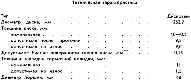
The brake disc is made of gray cast iron. The friction surfaces of the disc on the brake linings are processed with great precision, the allowable non-flatness and non-parallelism is 0.02 mm. Dents and porosity are not allowed on the friction surfaces of the disc, since surface defects will contribute to the rapid wear of the brake pad linings.
