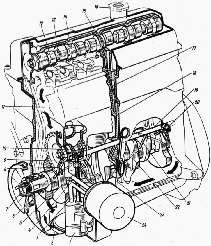
Pic. 24. Lubrication system:
1 - oil pump; 2 - oil sump; 3 - oil supply channel from the pump to the filter; 4 - horizontal channel for supplying oil from the filter to the oil line; 5 - channel for supplying oil to the drive gear of the oil pump and the ignition distributor; 6 - channel in the neck of the crankshaft; 7 - front crankshaft oil seal; 8 - oil supply channel from the oil line to the main bearing and to the oil pump drive shaft and ignition distributor; 9 - gear drive oil pump and ignition distributor; 10 - roller drive oil pump and ignition distributor; 11 - channel for draining oil; 12 - channel in the camshaft cam; 13 - main channel in the camshaft; 14 - channel in the camshaft bearing journal; 15 - annular groove on the middle bearing journal of the camshaft; 16 - oil filler cap; 17 - inclined channel in the cylinder head; 18 - vertical channel in the cylinder block; 19 - oil line; 20 - oil pressure warning lamp sensor; 21 - oil supply channel to the main bearing; 22 - oil supply channel from the main bearing to the connecting rod; 23 - oil level indicator; 24 - oil filter.
Oil from the oil crankcase 2 is sucked in by the oil pump 7 and is fed through channel 3 in the cylinder block to the full-flow filter 24. From the filter, the oil enters the oil line 19, to lubricate the main bearings and two bearings of the roller 10 of the oil pump drive. From the main bearings, oil through the internal channels of the crankshaft lubricates the connecting rod bearings and from them through the holes in the lower heads of the connecting rods spray lubricates the cylinder walls.
Oil is supplied to the supports and cams of the camshaft through channels 17 and 18 in the block and cylinder head and through the main channel 13 in the camshaft. The camshaft drive chain is lubricated by splashing oil, which is squeezed out of the front camshaft bearing and the front oil pump drive shaft bushing.
The oil pressure warning light sensor 20 is mounted on the cylinder block and connected to the oil line. The signal lamp in the instrument cluster comes on when the engine is started and must go out when the engine is running, when the pressure is sufficient for normal lubrication.
In some cases, when the oil is heated, the lamp may burn when the engine is running at low idling.
Normal oil pressure at 85°C and 5600 rpm 3.5-4.5 kgf/cm2. Minimum oil pressure at minimum engine speed (850-900 rpm) must be at least 0.5 kgf/cm2.
Oil pump
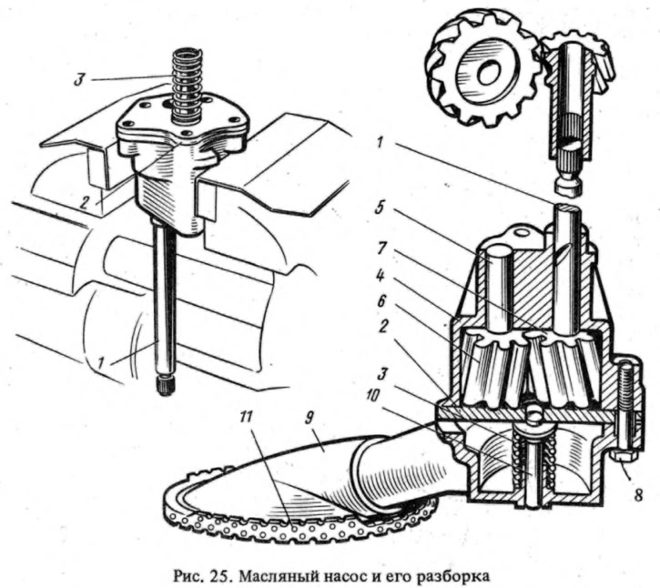
gear type (pic. 25), is installed inside the crankcase and is attached to the cylinder block with two bolts. The drive gear 7 is fixedly fixed on the roller 1 and is supplied as a spare part complete with the roller. The driven gear 6 rotates freely on the axis 5 pressed into the pump housing 4.

An oil inlet pipe 9 with a filter mesh and a built-in pressure reducing valve 10 is attached to the pump housing with bolts 8 under the cover 2. The valve actuation pressure is provided by a spring 3 of appropriate elasticity. The pressure is not adjustable. The length of the pressure reducing valve spring in the free state 38 mm, under load (6,35±0,2) kgf - 20 mm.
Oil pump drive - chain transmission from the crankshaft sprocket to the roller sprocket 10 (see fig. 24) oil pump drive and ignition distributor, which is installed in the cylinder block in steel-aluminum bushings. The roller has a helical gear engaged with gear 9 of the oil pump drive and the ignition distributor. Gear 9 rotates in a ceramic-metal bushing pressed into the cylinder block. The slotted hole of the gear includes the splines of the oil pump shaft and the ignition distributor.
Oil filter
Full-flow, non-separable, a paper filter element is installed in its steel housing. the filter has a rubber anti-drain valve that prevents oil from draining from the system when the engine is stopped, and a bypass valve that operates when the filter is clogged.
The filter is screwed onto the fitting of the cylinder block and connected by channels to the oil pump and the oil line. To remove it, use A.60312 tool (see fig. 45). When installing the filter, it is recommended to wrap it manually without a device.
Crankcase ventilation
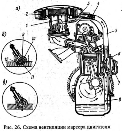
Crankcase gases are sucked off through hose 5 (pic. 26, a), put on the pipe cover 6 of the breather, into the exhaust manifold 3, located under the air filter. From the exhaust manifold, gases can be sucked off in two ways: into the air filter, bypassing the filter element 2, and then through the carburetor into the engine intake pipe; through hose 1 (see fig. 26, a) into the spool of the carburetor (pic. 26, b and c) and further into the throttle space of the carburetor.

The spool device regulates the mode of suction of crankcase gases at different crankshaft speeds. The device consists of a spool on the axis 9 of the throttle valve of the primary chamber and a calibrated hole 12. The spool has a groove 11.
At low speed (pic. 26, a) crankshaft (with closed throttle) the vacuum at the carburetor inlet is insignificant, and the bulk of the gases are sucked out through hose 1, and then through a calibrated hole 12 (rice, 26, 6) into the throttle body of the carburetor. The calibrated orifice limits the amount of exhaust gases, and ventilation has little effect on the vacuum behind the throttle valve.
With an increase in the frequency of rotation of the crankshaft when the throttle valve is opened, the spool 10 rotates and opens an additional path for gases along the groove 11 (pic. 26, in). Gases are sucked off both through hose 1 and into the air filter. The total amount of exhausted gases increases.
At high engine speed (carburetor primary throttle fully open) the bulk of the gases are sucked into the air filter in the space behind the filter element.
During engine operation, crankcase gases pass through the oil separator 7, where the oil is separated and flows down the tube 8. A flame arrester 4 is installed in the hose 5, which prevents the flame from breaking into the crankcase when "clapping" into the carburetor.
