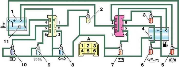
Wiring diagram for instrument cluster (back view)

1 - coolant temperature gauge; 2 – a lamp of illumination of a combination of devices; 3 – a control lamp of a reserve of fuel; 4 - fuel gauge; 5 - control lamp of the parking brake and brake fluid level; 6 – a control lamp of pressure of oil; 7 – a control lamp of a charge of the accumulator battery; 8 – a control lamp of indexes of turn; 9 – a control lamp of external illumination; 10 – a control lamp of a high beam of headlights; 11 - device protection diode; A - the order of conditional numbering of plugs in the blocks of the instrument cluster
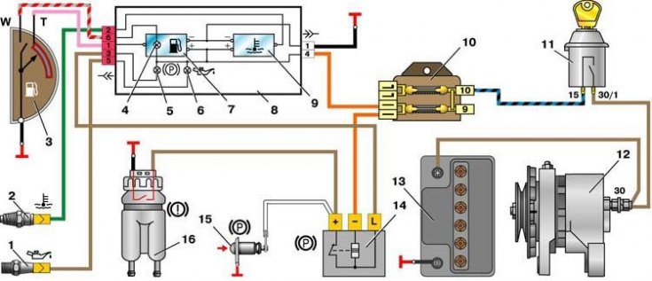
Scheme of switching on control devices

1 – the gauge of a control lamp of pressure of oil; 2 – the gauge of the index of temperature of a cooling liquid; 3 – sensor of level indicator and fuel reserve; 4 – a control lamp of a reserve of fuel; 5 - control lamp of the parking brake and brake fluid level; 6 – a control lamp of pressure of oil; 7 - fuel gauge; 8 – a combination of devices; 9 - coolant temperature gauge; 10 - fuse block; 11 - ignition switch; 12 - generator; 13 - battery; 14 - relay-breaker of the parking brake control lamp; 15 – the switch of a control lamp of a parking brake; 16 - brake fluid level sensor;
The schemes for switching on the control lamps of the battery charge, high beam headlights, side light and direction indicators are given earlier in fig. Generator System Wiring Diagram, Scheme for switching on outdoor lighting, Headlight switching circuit and Scheme of inclusion of direction indicators.
Coolant temperature gauge
1. When the pointer needle is constantly at the beginning of the scale, then with the ignition on, disconnect the wire from the pointer sensor and connect the wire tip to ground.
2. If the arrow deviates, then the sensor is faulty and must be replaced.
3. If the arrow does not deviate, then remove the combination from the instrument panel, disconnect the wiring harness block from the right (red) instrument cluster pads and, with the ignition on, connect plug 2 (see fig. Wiring diagram for instrument cluster (back view)) red block of the instrument cluster with a mass. The deviation of the arrow in this case will indicate the serviceability of the device and the damage to the wire connecting the indicator sensor to the instrument cluster.
4. If the arrow does not deviate, then replace the temperature gauge or instrument cluster.
5. When the pointer needle is constantly in the red zone, then with the ignition on, disconnect the wire from the sensor. In the event of a sensor malfunction, the pointer should return to the beginning of the scale. If it remains in the red zone, then either the wire is shorted to ground, or the device is damaged.
6. The serviceability of the device can be checked by disconnecting the wiring harness block from the right (red) instrument cluster pads. With the ignition on, the arrow should be at the beginning of the scale.
Fuel gauge
The verification procedure is similar to that described above. In this case, it must be borne in mind that the plug «W» the pointer sensor is connected to the wire that goes to the fuel reserve control lamp, and to the plug «T» - a wire going to the pointer itself.
If the pointer needle is constantly at the beginning of the scale and does not deviate after shorting with the mass of the tip of the wire disconnected from the plug «T» sensor, then check the device. To do this, remove the instrument cluster, disconnect the right (red) block and, with the ignition on, connect the plug 1 of the red block of the instrument cluster to ground. With a working device, the arrow should deviate to the end of the scale.
When the pointer needle is constantly at the end of the scale, the device can be checked for proper operation by disconnecting the pink wire from the pointer (to the plug «T» sensor). In this case, for a serviceable device with the ignition on, the arrow should be against the mark «0». The serviceability of the device can be checked by disconnecting the wiring harness block from the right (red) instrument cluster pads. With the ignition on, the arrow should be at the beginning of the scale.
