If the brake light switch is too close to the pedal, then it does not return to its original position, valve 9 (see fig. 193), pressing against the body 22, separates the cavities A and E and the wheels are not completely released when the pedal is released.
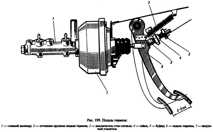
The position of the brake light switch is adjusted by moving it with the nut 4 released (see fig. 199). Install it so that the brake light buffer 5 slightly touches the pedal stop 6, while the pedal free play should be 3-5 mm. At the end of the adjustment, tighten the nut 4. It must be remembered that the brake pedal free play must be adjusted when the engine is not running.
If by moving the brake light switch it is not possible to eliminate the incomplete release of the brake mechanisms, then disconnect the brake master cylinder from the vacuum booster and check the protrusion of the adjusting bolt 28 (see fig. 193) relative to the mounting plane of the master cylinder flange (size 1.25-0,2 mm), as stated earlier (see section «vacuum booster»). Set this dimension by holding the end of the rod 3 with a special key, and wrapping or unscrewing the bolt 28 with another key, as indicated in the section «Measurement of the protrusion of the vacuum booster rod».
