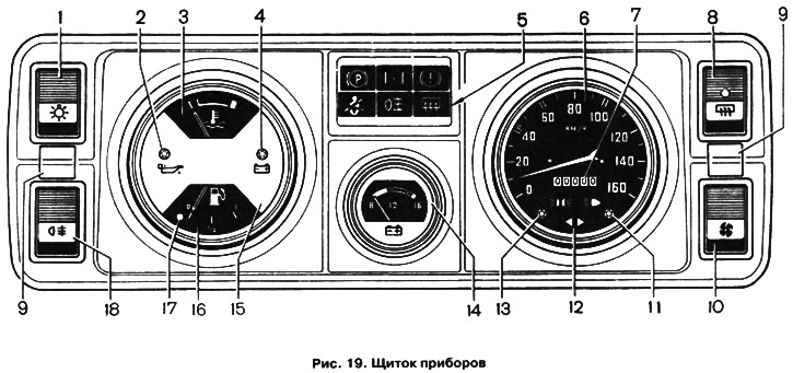
- 1 - outdoor lighting switch.
- 2 - indicator of insufficient oil pressure in the engine lubrication system.
- 3 - liquid temperature gauge in the engine cooling system. The transition of the arrow to the red zone of the scale indicates overheating of the engine.
- 4 - battery charge indicator.
- 5 - block of signaling devices.
- 6 - speedometer.
- 7 - summing counter of the distance traveled.
- 8 - rear window heating switch.
- 9 — plugs of screws of fastening of a panel of devices.
- 10 - three-position heater electric fan switch.
- 11 - signaling device for switching on the high beam.
- 12 - signaling device for turning on direction indicators.
- 13 - signaling device for turning on side lights.
- 14 - voltmeter. With the ignition on and the engine off, the voltmeter shows the voltage at the battery terminals, and with the engine running, the voltage generated by the generator. The arrow of the device with the engine running in the red zone of the scale indicates the discharge of the battery due to a weak tension of the fan belt or a malfunction of the generator itself, and in the white zone of the scale it indicates an unsteady charge-discharge mode. The arrow of the device in the green zone indicates normal voltage, and its transition to the red zone at the end of the scale indicates overcharging of the battery due to a malfunction of the generator.
- 15 - instrument cluster.
- 16 - fuel gauge.
- 17 - fuel reserve signaling device.
- 18 - rear fog lights switch.
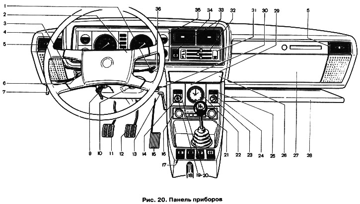
In a variant version, the instrument panel shown in fig. 20.

- 1 - switch lever for windshield wipers and washer and headlights.
- 2 - horn switch.
- 3 — the lever of the switch of indexes of turn.
- 4 - headlight switch lever.
- 5 - side nozzles of the ventilation and interior heating system.
- 6 - hydrocorrector headlights (see pos. 8, fig. 18).
- 7 - engine hood lock drive lever.
- 9 - ignition switch.
- 10 - alarm switch (see pos. 13, fig. 18).
- 11 - clutch pedal.
- 12 - brake pedal.
- 13 - heater cover lever.
- 14 - instrument lighting switch (see pos. 6, fig. 18).
- 15 - accelerator pedal.
- 16 - socket for installing radio equipment. Installation of radio equipment should be carried out only on certified technical equipment with a mandatory mark in the service book.
- 17 - key switch panel. Depending on the vehicle model, the following switches are installed: outdoor lighting switch key; rear window heating switch key; heater electric fan switch key; rear fog light switch button.
- 18 - parking brake lever (see pos. 18, fig. 18).
- 19 - signaling device for unfastened seat belts *.
- 20 - backup signaling device *. On a vehicle equipped with fuel injection, a signaling device is connected "Check engine".
- 21 - gear lever.
- 22 - hours. By rotating the extended or recessed transfer handle (depending on watch type) arrows are being translated.
- 23 - cigarette lighter (see pos. 19, fig. 18).
- 24 - signaling device for turning on the rear window heating.
- 25 - liquid level indicator in the hydraulic brake reservoir.
- 26 - ashtray.
- 27 - glove box.
- 28 - storage shelf.
- 29 - upper insert.
- 30 - carburetor air damper control knob (see pos. 15, fig. 18).
- 31 - plug.
- 32 - block of levers for controlling the ventilation and heating system.
- 33 - central nozzles of the ventilation and interior heating system.
- 34 - heater electric fan switch. On a car with a body "station wagon" the rear window wiper and washer switch is installed.
- 35 - instrument cluster.
- 36 - handle for resetting the daily mileage counter. Resetting is carried out counterclockwise with the vehicle stopped.
* It is installed on some cars equipped with this system, on the rest a plug is installed.
