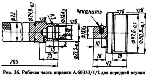
Check the ovality of the auxiliary drive shaft bushings, their pressing into the sockets, and the alignment of the lubrication hole in the front bushing with the channel in the cylinder block. Turning the bushings in the cylinder block is not allowed. Measure the diameters of the bushings and the roller and determine the gaps between them. If the gaps are greater than 0.15 mm, and also if there is damage to the surface, replace the bushings with new ones. A mandrel is used to replace bushings (pic. 36) A.60333/1/2. After pressing the bushings, they are processed with reamers to the dimensions given in tab. 1. To ensure full alignment of the bushings, machine both bushings at once with A.90353 reamer.
The auxiliary drive shaft must not have damage to the bearing journals, and the shaft gear must not have visually noticeable wear and chipping of the teeth. The roller should also be discarded if the bearing journals are worn: the front one up to a diameter of 48.01 mm, the rear one up to a diameter of 21.94 mm.
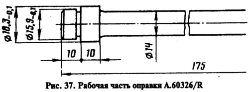
Loose fitting and ovality of the bushing of the oil pump drive gear and ignition distributor are not allowed. The inner surface of the bushing must be free of burrs. For pressing and pressing out, use a mandrel 1 (pic. 37) A.60326/R. After pressing the sleeve, expand to a diameter of 16.016-16.037 mm.