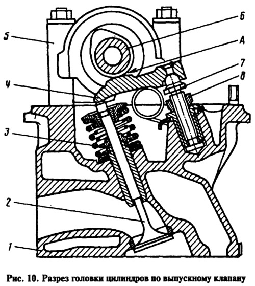
The valve guides are made of cast iron and are pressed into the cylinder head with an interference fit. On the outer surface of the guide bushings there is a groove where the retaining ring is inserted. It ensures the accuracy of the position of the bushings when they are pressed into the cylinder head and protects the bushings from possible falling out.
The holes in the bushings are processed after pressing them into the cylinder head. This provides a minimum tolerance for the bore diameter and the accuracy of its location in relation to the seat and valve facets. The bores of the guide bushings have spiral grooves for lubrication. The inlet valve bushings are grooved up to half the length of the hole, and the exhaust valve bushings are grooved along the entire length of the hole.
Oil deflector caps 3 made of heat-oil-resistant rubber with a steel reinforcing ring are put on top of the guide bushings. The caps surround the valve stem and serve to reduce oil penetration into the combustion chamber through the gaps between the valve guide and the valve stem.
On engines 2105, cylinder head 2105-1003015 is used, and on other engines (2101 and 2103) the same unified cylinder head 21011-1003015-10 is installed (number is cast on the left side of the cylinder head). These cylinder heads differ only in the front. The 21011 heads have an opening for the camshaft drive chain here, while the 2105 heads do not have such an opening.
