Camshaft
On the bearing journals of the camshaft, scuffing, nicks, scratches, aluminum enveloping from bearing housings are not allowed. On the working surfaces of the cams, wear of more than 0.5 mm, as well as scuffing and wear of the cams in the form of a cut, are not allowed.
Install the camshaft with the outer journals on two prisms placed on the calibration plate, and measure the radial runout of the middle journals with an indicator, which should be no more than 0.04 mm. If the runout exceeds the specified value, then straighten the shaft on a straightening press.
When replacing the camshaft with a new one, the valve actuating levers must also be replaced at the same time.
Camshaft bearing housing
Rinse and clean before checking (in particular oil passages), and then check the bore diameters in the bearings and camshaft journals. If the difference between the diameters of the holes in the supports and necks exceeds 0.2 mm, replace the housing.
The inner bearing surfaces of the bearing housing must be smooth and free of burrs. If there is damage, replace the bearing housing.
Tensioner
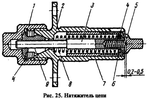
To check chain tensioner parts (pic. 25) it needs to be disassembled. At the same time, unscrew cap nut 7 from body 2, remove cracker 9 and spring ring 4, then remove plunger 7, spring 5 and rod 3 together with spring 8 and washer 6.

After disassembling the chain tensioner, check for signs of scoring on parts 9 and 3, and for deep scratches on the mating surfaces of the shoe and plunger of the chain tensioner. If there is damage, replace parts.
In addition, check the elasticity of the tensioner spring 8. Its length in the free state should be equal to 62 mm, under a load of 12.5±0.6 kgf - 47 mm, and under a load of 18.5±1.0 kgf - 40 mm.
If the spring is less elastic, replace it. Also check for wear on the shoe and damper. If there are deep grooves on the surface of the rubber or the rubber is worn down to a metal base, then replace the shoe and damper.
Camshaft drive chain
Wash the chain in kerosene before checking, and then check the condition of the links. Chips, cracks and other damage are not allowed on the rollers and cheeks of the chain.
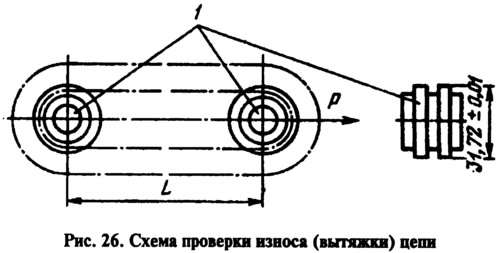
When the engine is running, the chain stretches. It is considered operational if the tensioner provides its tension, i.e. if the chain is extended by no more than 4 mm. Check the chain extractor on a device with two rollers 7 (pic. 26), on which the chain is put on. The hood is determined by the distance between the axes of the rollers. But before measuring the distance, stretch the chain with a force P = 30 kgf, then reduce it to 15 kgf, increase the force again to 30 kgf, and then again reduce it to 15 kgf and take a measurement. For a new chain, the distance between the axes of the rollers is 485.775+0,5+0,1 mm for engines 2101 and 495.3+0,5+0,1 mm for engines 2103. The chain is replaced if it is extended to 490 mm for engines 2101 or up to 499.5 mm for engines 2103.

Camshaft drive belt
The surface of the toothed part must be with a clear tooth profile, without wear, wrinkles, cracks, undercuts and delamination of the fabric from the rubber. On the end surfaces, delamination and fraying should not be observed, but a slight protrusion of the fringe of the fabric is allowed. The surface of the outer flat part must be even, without folds, cracks, depressions and bulges.
Belt tensioner
The working surface of the tension roller must be smooth, without nicks and burrs.
The ball bearing of the tension roller should rotate smoothly, without jamming.
Check the elasticity of the spring of the tension roller bracket along its length in the free state and under load. The length of the spring, measured between the inner edges of the rounded ends of the spring, should be 70 mm in the free state, and 13.2±1.3 kgf -120 mm under load.
