Engine 2105
Install the washed and cleaned cylinder block on the stand and wrap the missing studs. Lubricate the cylinders, pistons, oil seals, bearing shells and crankshaft thrust washers with engine oil.
Place inserts without a groove on the inner surface in the seat of the middle main bearing and in its cover, and inserts with a groove * in the remaining sockets and corresponding covers.
* Since 1987, all lower main bearing shells have been used without grooves on the inner surface.
Lay the crankshaft in the main bearings and insert two thrust half rings into the sockets of the rear support with recesses to the thrust surfaces of the crankshaft, and on the front side of the rear support, place a steel-aluminum semi-ring, and on the rear side - a cermet (yellow color).
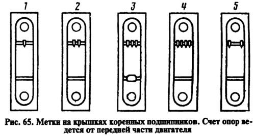
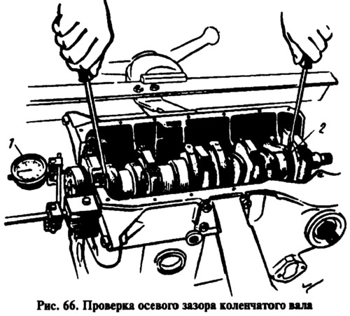
Install the main bearing caps according to the marks (pic. 65). Then check the axial clearance of the crankshaft (clearance between thrust washers and thrust surfaces of the crankshaft). To do this, set indicator 7 as shown in fig. 66, and, moving the shaft with 2 screwdrivers, check the axial clearance on the indicator, which should be in the range of 0.06-0.26 mm. If the gap exceeds 0.26 mm, replace the thrust half rings with new or repair ones, increased by 0.127 mm.
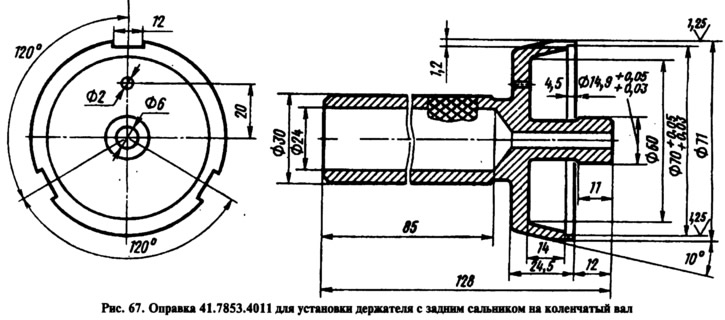
Put the gasket of the rear oil seal holder on the crankshaft flange, and insert the bolts of the front cover of the clutch housing into the sockets of the holder. Put the holder with the stuffing box on the mandrel 41.7853.4011 (pic. 67) and, moving it from the mandrel to the crankshaft flange, attach it to the cylinder block.
Install the front cover 6 along the two centering bushes (see fig. 61) clutch housing.
Install the flywheel on the crankshaft so that mark A (see fig. 9) was against the axis of the connecting rod journal of the fourth cylinder. Then block the flywheel with lock A.60330/R (see fig. 61) and secure to the crankshaft flange.
With bushing from set 02.7854.9500 for motors 2105 or A.60604 (pic. 68) for engines 2101 and 2103, or using the adjustable sleeve 67.7854.9517, insert the pistons with connecting rods into the cylinders. In this case, the P mark on the pistons must be turned towards the front of the engine.
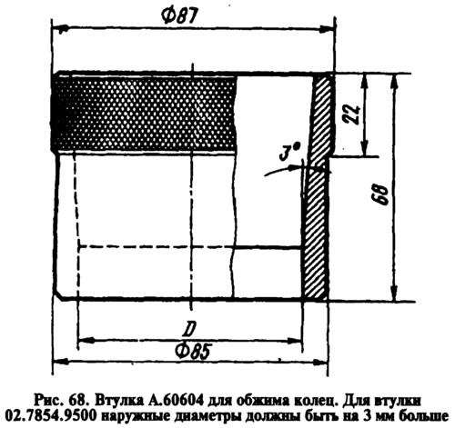
Bushing kits for crimping piston rings when installing pistons in cylinders include four bushings - one for standard size pistons and three for oversized (repair) piston size. Therefore, it is necessary to select a bushing suitable for the size of the piston to be installed.
Sleeve inner diameter D (see fig. 68) is made 0.2 mm less than the nominal diameter of the cylinder and with a tolerance of +0.04 mm. For example, for a normal cylinder size of 76 mm, the diameter D is taken as 75.98+0,04 mm; for the first cylinder oversize (79.4 mm) on the engine 2105 diameter D is taken 79.38+0,04 mm etc.
Install the liners in the connecting rods and connecting rod caps, connect the connecting rods to the crankshaft journals and tighten the connecting rod bolts. Install the caps so that the cylinder number on the cap is opposite the cylinder number on the bottom of the connecting rod.
Install the cylinder head with gasket on the two centering bushings on the block and tighten the mounting bolts in two steps, as indicated in section «Cylinder head and valve train».
Wrap the adjusting bolts of the valve levers deeper so that the levers are lowered and do not interfere with the installation of the bearing housing with the camshaft.
Install the accessory drive shaft and secure it with the thrust flange. Attach the holder with the stuffing box and gasket to the cover of the camshaft drive, without finally tightening the fastening nuts.
Press the oil seal of the auxiliary drive shaft into the cover and attach the cover together with the gasket to the cylinder block, without finally tightening the nuts and bolts.
Center with drift 67.7853.9548 (tubular with outer diameter 40+0,06+0,05 mm and internal 16+0,02 mm) cover position relative to the accessory drive shaft and tighten the bolts and nuts securing the camshaft drive cover.
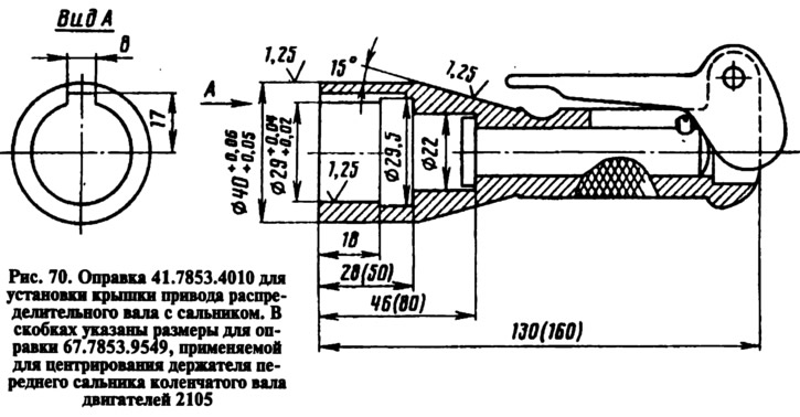
Mandrel 67.7853.9549 (see fig. 70, similar to mandrel 41.7853.4010, but has a larger hole length and depth) center the position of the crankshaft front oil seal holder and tighten the holder fastening nuts.
Install the toothed pulley on the accessory drive shaft. Lubricate the pulley mounting bolt with KLT-75T sealant and tighten it, holding the pulley from turning with tool 67.7811.9509. Install the toothed pulley on the crankshaft.
Assemble the bearing housing with the camshaft, thrust flange, oil seal holder and pulley, and then install it on the cylinder head (see section «Removal and installation of a camshaft»).
Attach the bracket with the tension roller to the cylinder block, without finally tightening the fastening bolts, and turn the bracket to the extreme left position.
Turn the crankshaft so that the mark on the toothed pulley matches the mark on the camshaft drive cover (similar to the location of the marks on the sprocket and cylinder block, see fig. 24). Also turn the camshaft pulley until the alignment marks on the pulley and the camshaft bearing housing are aligned (see fig. eleven).
Slide the toothed belt over the crankshaft pulley, then over the accessory drive shaft pulley and over the tensioner pulley by tightening the belt counterclockwise. Then put the belt from the front end onto the camshaft pulley, pressing the tension roller bracket to the right, and install the tension spring.
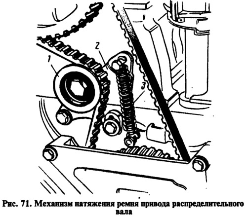
Slowly rotate the crankshaft two turns clockwise while keeping the belt under constant tension, and hold the crankshaft when the crankshaft stops to prevent the belt from loosening. In this case, the tension spring will set the required belt tension. Check match marks (see rice. eleven and rice. 24). If the marks match, then tighten the tension roller bracket mounting bolts, first the right and then the left bolts.
If the marks do not match, then repeat the installation of the belt by adjusting the position of the camshaft pulley.
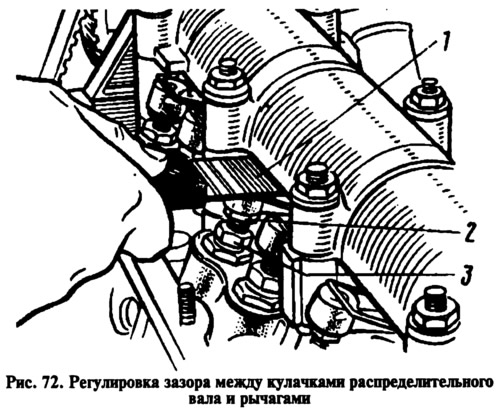
Adjust the clearance between the camshaft cams and the valve actuating levers.
Install the cylinder head cover with gasket and tighten its nuts in the sequence shown on rice. 13.
Install the lower, middle and upper camshaft belt drive guards.
Install the alternator drive pulley on the crankshaft and secure it with a bolt, blocking the flywheel with a retainer (see fig. 61).
Lubricate the oil filter O-ring with engine oil and install it by hand screwing it to the fitting on the adapter.
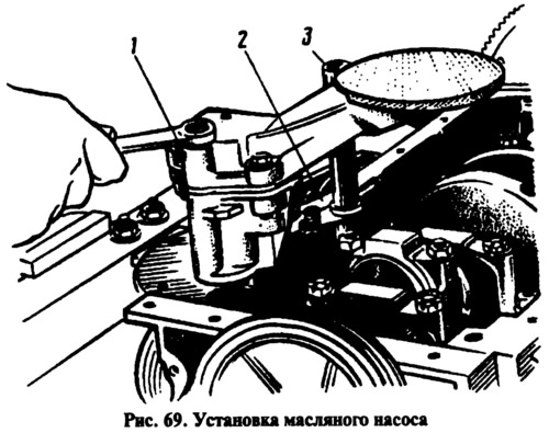
Install the crankcase ventilation oil separator, breather cover and fasten the retainer 2 (pic. 69) drain tube 3 oil separator. Install oil pump 1 and then oil sump with gasket.
Install the coolant pump, alternator bracket and alternator. Put the alternator drive belt on the pulleys and adjust its tension (see section «Engine settings»).
On the cylinder head, install the inlet pipe of the heater radiator and the outlet pipe of the cooling jacket. Attach the heater core outlet pipe to the coolant pump and exhaust manifold. Install control gauges.
Using guide mandrel 41.7820.4006, install the oil pump drive gear and ignition distributor into the cylinder block.
Install the ignition distributor, for which:
- remove the cover from the ignition distributor, check and, if necessary, adjust the gap between the breaker contacts;
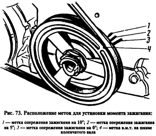
- turn the crankshaft until the start of the compression stroke in the 1st cylinder, and then, continuing to turn the crankshaft, align mark 4 with mark 2 (see fig. 73);
- turn the rotor to such a position that its outer contact will be directed towards the contact of the 1st cylinder on the ignition distributor cover, and, holding the distributor shaft from turning, insert it into the socket on the cylinder block so that the center line passing through the spring latches covers, was approximately parallel to the centerline of the engine;
- fix the ignition distributor on the cylinder block, install the cover and connect the wires;
- screw the spark plugs into the cylinder head, install the key 67.7812.9515 on them (tubular face 21 mm with a square hole for the spindle of the torque handle) and tighten with a torque handle;
- install the fuel pump according to the instructions given in section «Removal and installation of components of the power system». Install the carburetor with gasket and attach the hoses to it. Close the carburetor with a service plug and fill the oil in the neck on the cylinder head cover.
Engines 2101, 2103
The assembly of these engines differs in the operations for assembling the front of the engines. After installing the cylinder head on these engines, perform the following operations:
- Install the sprocket on the crankshaft, and the auxiliary drive shaft in the cylinder block and secure it with a thrust flange.
- Turn the flywheel so that the mark on the crankshaft sprocket aligns with the mark on the cylinder block (see fig. 24).
- put on (previously) sprocket onto the camshaft assembled with the bearing housing and turn it so that the mark on the sprocket is against the mark on the bearing housing (see fig. eleven). Then remove the sprocket and, without violating the position of the camshaft, install the bearing housing on the cylinder head and secure it by tightening the nuts in a certain sequence (see fig. 23). After that, install a chain guide on the cylinder head.
Install the camshaft drive chain in the following sequence:
- lubricate the chain with engine oil, put it on the camshaft sprocket and insert it from above into the drive cavity, installing the sprocket so that the mark on it matches the mark on the bearing housing (see fig. eleven). Then install the lock washer and the sprocket mounting bolt, without tightening it all the way;
- install the sprocket, lock washer and bolt on the auxiliary drive shaft, without completely tightening it;
- put the chain on the crankshaft sprocket and install the chain tensioner shoe and tensioner without tightening the cap nut so that the tensioner spring can press the shoe;
- wrap the chain restrictor pin in the cylinder block;
- turn the crankshaft two turns in the direction of rotation to obtain the correct chain tension and check that the marks on the sprockets match those on the cylinder block (see fig. 24) and on the bearing housing (see fig. eleven). If the marks match, then, after blocking the flywheel with lock A.60330/R, finally tighten the sprocket bolts, chain tensioner cap nut and bend the sprocket bolt lock washers. If the marks do not match, then repeat the chain installation operation.
Adjust the clearance between the camshaft cams and the valve actuating levers. Install the camshaft drive cover with gasket and oil seal on the cylinder block, without finally tightening the bolts and nuts. Mandrel 41.7853.4010 (pic. 70) center the position of the cover relative to the end of the crankshaft and finally tighten the nuts and bolts of its fastening. Install the crankshaft pulley and tighten the ratchet.
Next, install the oil filter and continue the assembly, as on the 2105 engine.
