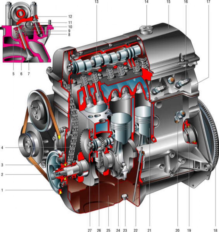
Engine VAZ-2106

1 - crankshaft pulley; 2 - generator drive belt; 3 - front cuff of the crankshaft; 4 - camshaft drive circuit; 5 - spring plate; 6 - guide sleeve; 7 - valve; 8 - internal spring; 9 - outer spring; 10 – lever spring; 11 - adjusting bolt; 12 – valve drive lever; 13 - camshaft; 14 - oil filler cap; 15 – a cover of a head of the block of cylinders; 16 - spark plug; 17 – a head of the block of cylinders; 18 - flywheel; 19 – a back cuff of a cranked shaft; 20 - oil pressure sensors; 21 - piston; 22 - oil level indicator; 23 - oil drain plug; 24 - connecting rod; 25 - oil pan; 26 - roller drive auxiliary units; 27 - crankshaft
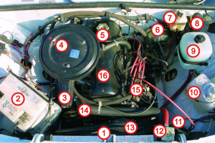
Placement of the main components and assemblies in the engine compartment

1 - radiator; 2 - storage battery; 3 - suction pipe; 4 - air filter housing; 5 - plug of the oil filler neck; 6 - vacuum brake booster; 7 - reservoir of the brake system; 8 – a reservoir of a hydraulic drive of deenergizing of coupling; 9 - expansion tank of the cooling system; 10 - washer reservoir; 11 - ignition coil; 12 - cover (cork) radiator; 13 - electric fan; 14 – the top hose of a radiator; 15 - breaker-distributor; 16 – a cover of a head of the block of cylinders
Design Description
The car is equipped with a gasoline, four-stroke, four-cylinder, in-line, eight-valve engine, with an overhead camshaft. The power system is carburetor. The order of operation of the cylinders: 1-3-4-2, counting - from the crankshaft pulley.
The VAZ-2103 engine differs from the VAZ-2106 engine in a smaller cylinder diameter (76 mm vs 79) and, accordingly, the cylinder block, the size of the pistons and piston rings, as well as the cylinder head gasket. The block heads for both engines are the same and their parts are interchangeable. Engine cylinders are arranged vertically in one row and combined into a block. On top of it, a block head common to all cylinders is installed. From below, the cylinder block is closed with a stamped steel pan, which also serves as a container for oil.
The pistons have two compression rings and one oil scraper ring. The crankshaft rotates in five bearings in the cylinder block. From the pulley at its front end, a V-belt drive drives the generator and coolant pump located on the right side of the engine.
In front of the engine there is a camshaft drive and an auxiliary drive shaft: ignition distributor, fuel and oil pumps. The drive is carried out by a two-row bush-roller chain.
On the right side of the engine, in addition to the generator, there is an exhaust manifold, a starter and an intake pipe with a carburetor and an air filter. The oil filter is on the left side.
To install the engine assembly with the gearbox and clutch, a three-point suspension scheme was used. Two front supports are located on both sides of the cylinder block and are attached to the cross member of the vehicle's front suspension. The rear support is located on the gearbox and rests on a cross member fixed under the floor of the body.
The elastic cushions of the front supports consist of rubber with vulcanized steel washers and mounting bolts. To increase the rigidity of the supports, there are springs in the central hole of the pillows resting on insulating rings, and rubber-metal buffers are located inside the springs to mitigate shocks. The cushions are attached to the brackets with intermediate plates. The right pillow is protected from heating from the side of the exhaust pipe of the mufflers by a protective cover.
The rear support is also rubber-metal, it consists of three steel plates with rubber separating them. The middle plate is attached to the gearbox, and the outer ones are attached to the cross member of the rear engine mount. Between the shelves of the crossbar, steel spacers are placed to protect the shelves from deformation when the fastening bolts are tightened.
The cylinder block is made by casting from special high-strength cast iron. Holes for cylinders are bored directly in the block and additional inserts (cartridge cases) cylinders do not apply. Cylinders are honed to obtain a special profile and surface finish. By diameter, the cylinders are divided into 5 classes through 0.01 mm, denoted by the Latin letters A, B, C, D and E. The class of each cylinder is marked on the lower plane of the cylinder block.
The holes for the main bearings of the crankshaft are bored together with the bearing caps. Therefore, they are not interchangeable either with each other or with covers of other cylinder blocks. In order not to confuse the covers, markings are made on them. Bearing caps are attached to the cylinder block with self-locking bolts, the replacement of which with any other is unacceptable.
The accessory drive shaft rotates in two bushings pressed into the cylinder block. The front hub is steel-aluminum, and the rear one is ceramic-metal, bronze-graphite. Spare parts are supplied with bushings of nominal and repair sizes with an inner diameter reduced by 0.3 mm.
Pistons are cast from aluminum alloy. The outer surface of the piston is coated with a thin layer of tin to improve its adaptability to the cylinder walls. To compensate for uneven thermal expansion, the piston skirt has a complex shape. It is conical in height and oval in cross section. Therefore, it is necessary to measure the piston diameter only in a plane perpendicular to the piston pin and at a distance of 52.4 mm from the piston crown.
Outside diameter of pistons (same as cylinders) are divided into five classes: A, B, C, D and E through 0.01 mm, and according to the diameter of the hole for the piston pin - into three categories through 0.004 mm. The category is indicated by paint on the end (the first is blue, the second is green, the third is red). Piston class (latin letter) and category (number) marked on the bottom of the piston.
Pistons of classes A, C, E are supplied as spare parts, which are quite enough to select a piston for any cylinder, since pistons and cylinders are divided into classes with some overlap in size.
The hole for the piston pin is offset from the axis of symmetry by 5 mm to the right side of the engine. Therefore, the piston has a mark in the form of the letter P for the correct orientation of the piston in the cylinder. The label must face towards the front of the engine.
Since 1986, oversized pistons for all models of VAZ engines have been manufactured with an outer diameter increased by 0.4 and 0.8 mm. Until 1986, repair pistons for engines 2103 and 2106 were produced with an increase of 0.4; 0.7 and 1.00 mm.
The pistons of the 2103 and 2106 engines differ only in size (diameter).
Piston rings are made of cast iron. Top compression ring with barrel chrome outer surface. Bottom compression ring scraper type, phosphated.
The piston pins are pressed into the upper head of the connecting rod and rotate freely in the piston bosses. According to the outer diameter, the fingers are divided into three categories through 0.004 mm. The category of the finger is marked on its end with the corresponding color: 1st - blue, 2nd - green and 3rd - red.
Connecting rod steel, forged. The lower head of the connecting rod is detachable, connecting rod bearings are installed in it. The connecting rod is machined together with the cap and therefore they are not interchangeable with caps of other connecting rods. In order not to confuse the connecting rod caps during assembly, on the connecting rod and its cap (side) there is a stamp of the number of cylinders in which they are installed. When assembling, the numbers on the connecting rod and cap must be on the same side.
The crankshaft is cast from ductile iron and has five bearings (indigenous) necks hardened by high frequency current to a depth of 2–3 mm. At the rear end of the crankshaft there is a socket where the gearbox input shaft bearing is inserted. The lubrication channels in the crankshaft journals are closed with cap plugs, which are pressed in and tapped at three points for reliability.
To prolong the service life of the crankshaft, it is possible to regrind the crankshaft journals when their surfaces are worn or damaged. By grinding, the diameters of the necks are reduced by 0.25; 0.5; 0.75 and 1.00 mm.
The axial movement of the crankshaft is limited by two thrust half rings installed in the cylinder block on both sides of the rear main bearing. A steel-aluminum semi-ring is placed on the front side of the bearing, and a metal-ceramic semi-ring on the back side (yellow color).
Inserts of main and connecting rod bearings are thin-walled, bimetallic, steel-aluminum. Inserts for the 1st, 2nd, 4th and 5th main bearings have a groove on the inner surface (since 1987 the lower shells of these bearings have been installed without a groove). The center main bearing shells differ from the rest of the shells by the absence of a groove on the inner surface and a larger width. All connecting rod bearing shells are non-grooved, identical and interchangeable. Repair liners are made of increased thickness under the crankshaft journals, reduced by 0.25; 0.5; 0.75 and 1 mm.
The flywheel is cast iron and has a pressed steel ring gear for starting the engine with a starter. Flywheels are interchangeable, as they are balanced separately from the crankshaft. The flywheel with the crankshaft is centered by the front bearing of the gearbox input shaft.
The flywheel is attached to the crankshaft flange with six self-locking bolts, under which one common washer is placed. These bolts must not be replaced by any other.
