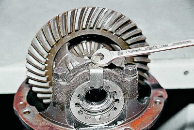
Having installed the gearbox on the workbench, the key «on 10» unscrew the two bolts securing the locking plates of the nuts of the differential bearings and remove the plates.
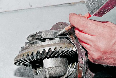
We make marks with a core on the bed and the corresponding bearing cap in order to install the caps in place during assembly.
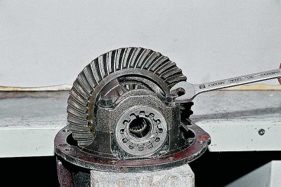
key «at 14» Loosen the bearing cap screws.
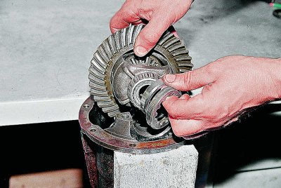
We take out the outer rings of the bearings and the adjusting nuts from the differential case.
If we do not change the bearings, then we mark the outer rings so as not to confuse them during installation, because the bearings are individually worn in and it is undesirable to dismantle them.
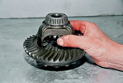
We check the absence of radial play in the gears of the axle shafts.
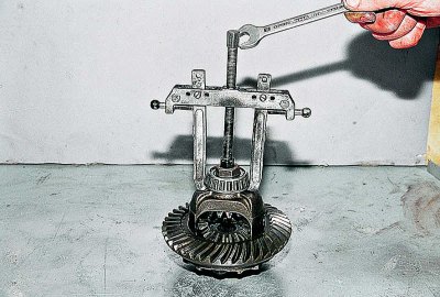
With a puller we press the inner rings of the tapered bearings.
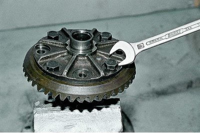
key «at 17» unscrew the eight bolts securing the driven gear to the differential housing and remove it.
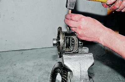
With a beard we knock out the axis of the satellites.
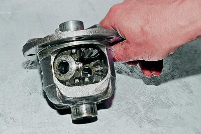
We turn the gears of the axle shafts and take out the satellite gears.
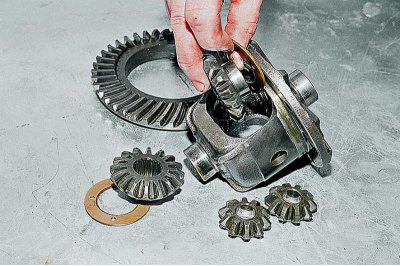
We take out the gears of the axle shafts with adjusting washers, marking their position.
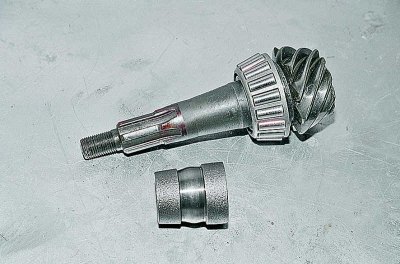
We take out the drive gear and the deformed spacer sleeve from the crankcase. When assembling the gearbox, we replace it with a new one.
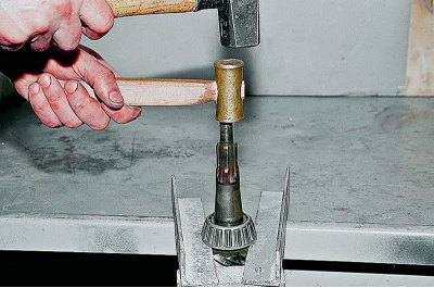
With a soft metal drift, we knock down the inner race of the tapered bearing from the drive gear shaft.
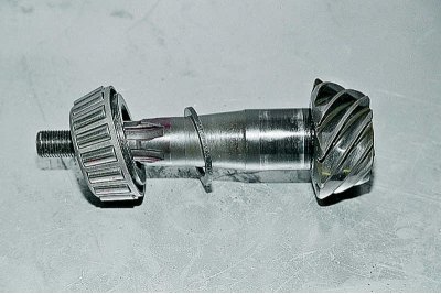
An adjusting ring is installed under the bearing, which ensures the correct relative position of the final drive gears.
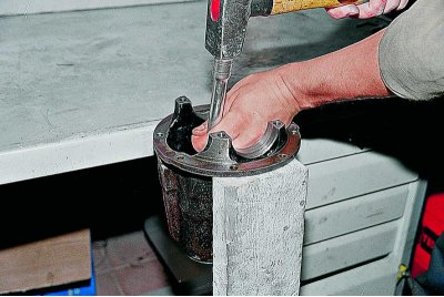
Using a suitable tool, knock out the outer races of the tapered bearings from the crankcase.
We thoroughly wash the gearbox parts in kerosene and carefully inspect. If at least one tooth is damaged (chipping, waves, risks, scuffs on working surfaces) replace the gears with new ones.
The edges between the tops and working surfaces of the teeth of the driven gear must be sharp. If the slightest nicks or roundings are visible, we replace the main pair with a new one.
Minor damage to the axis of the satellites, the necks of the gears of the axle shafts and their mounting holes are eliminated with fine sandpaper, followed by polishing.
When assembling, we replace the collar, flange nut and spacer sleeve with new ones.
If the gearbox is assembled in the old crankcase, then the change in the thickness of the adjusting ring of the drive gear can be calculated as the difference in the deviations in the dimensions of the manufacture of the old and new gears. Deviation in size with a sign «» or «–» engraved in hundredths of a millimeter on the pinion shaft.
For example, -12 is engraved on the old gear, and 4 on the new one. The difference between the two amendments will be 4- (–12) =16. This means that the new adjusting ring should be 0.16 mm thinner than the old one. With the reverse ratio of corrections (on the old 4, and on the new -12) the ring should be 0.16 mm thicker than the old one.
To more accurately determine the thickness of the adjusting ring, we make a fixture from an old drive gear.
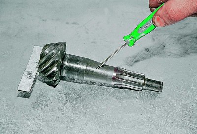
We weld a plate 80 mm long and trim it to a size of 50–0.02 mm relative to the plane under the bearing. The tapered part of the shaft is engraved with the serial number and the deviation in size.
We grind the seats under the bearings (can be processed with fine sandpaper) to a sliding landing.
We press the outer races of the front and rear bearings into the crankcase.
We install the inner ring of the rear bearing on the manufactured fixture and insert the fixture into the crankcase. We install the inner ring of the front bearing, the drive gear flange and tighten the nut with a torque of 0.8–1.0 kgf·m.
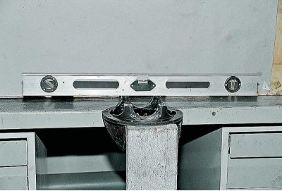
We expose the crankcase to a horizontal position according to the level.
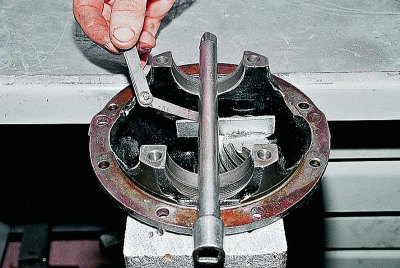
In the bed of bearings we put a round even rod (socket extension) and with a flat probe we determine the size of the gap between it and the fixture plate.
The thickness of the adjusting ring is defined as the difference between the gap and the size deviation of the new gear (taking into account the sign).
For example, the clearance value is 2.8 mm, and the gear size deviation is -15. So it is necessary to install an adjusting ring with a thickness of 2.8– (–0,15) =2.95 mm.
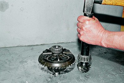
We install an adjusting ring of the required thickness on the shaft and, using a piece of pipe of a suitable size, press on the inner ring of the bearing.
We insert the shaft into the crankcase. We install a new spacer sleeve, the inner ring of the front bearing, the cuff and the drive gear flange.
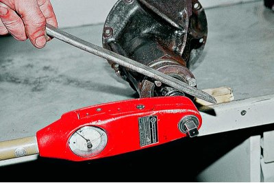
Gradually tighten the nut with a torque wrench to a torque of 12 kgf·m.
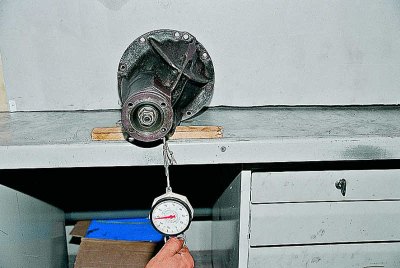
We determine the moment of cranking the drive gear shaft.
To do this, tightly wrap a strong thread around the neck of the flange in several turns and attach a dynamometer to it. The force at which the flange begins to rotate evenly should be 7.6–9.5 kgf (which corresponds to a torque of 16–20 kgf cm) (for new bearings). If the force is not enough, tighten the flange nut. In this case, the tightening torque should not exceed 26 kgf·m.
If, when tightening the nut, the turning torque exceeded 20 kgf cm (9.5 kgf), disassemble the gearbox and replace the spacer sleeve.
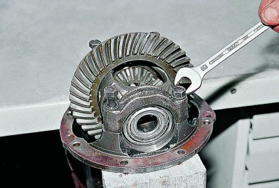
We install the differential housing together with the bearings in the crankcase and tighten the bolts of the bearing caps.
If axial play was found in the gears of the axle shafts, then during assembly we install new, thicker support adjusting rings. The side gears should fit snugly into the differential housing, but turn by hand.
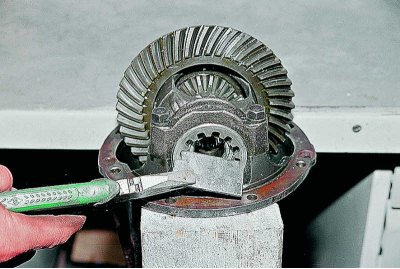
We make a wrench for tightening the adjusting nuts from a steel sheet with a thickness of 2.5–3 mm.
We adjust the clearance in the main pair and preload the differential bearings simultaneously, in several stages:
we wrap the nut on the side of the driven gear until the gap in the engagement is completely eliminated;
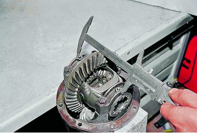
We measure the distance between the covers with a caliper;
we wrap the second nut until it stops and tighten it by 1-2 teeth of the nut. The distance between the caps should increase by approximately 0.1 mm;
by rotating the first nut, we set the required clearance in engagement of 0.08–0.13 mm. This is the least noticeable backlash in engagement with fingers, accompanied by a slight tap of tooth on tooth;
by hand, we control the constancy of the gap in the engagement and gradually tighten both nuts until the distance between the covers increases by 0.2 mm. This will provide the required bearing preload.
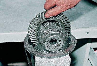
Slowly turn the driven gear three turns and at the same time feel the play in the engagement of each pair of teeth.
If it is uniform in all positions of the gears, then install the locking plates. Decrease (increase) backlash in any sector indicates deformation of the differential housing and the need to replace it or trim it on a lathe.
Locking plates are of two types: with one or with two legs.
Depending on the position of the slot of the nut, we install one of them.
