- Maximum recoil current at a voltage of 13 V and a rotor speed of 5000 rpm, A - 55
- Limits of regulated voltage, V — 14.1±0.5
- Maximum rotor speed, rpm — 13,000
- Gear ratio engine - generator - 1: 2.04
Generator type 37.3701 - alternating current, serves to power consumers of electrical energy and to charge the battery. It is a three-phase synchronous electric machine with electromagnetic excitation. To convert alternating current to direct current, a rectifier with six silicon valves is built into the generator. The voltage is regulated by a built-in microelectronic voltage regulator.
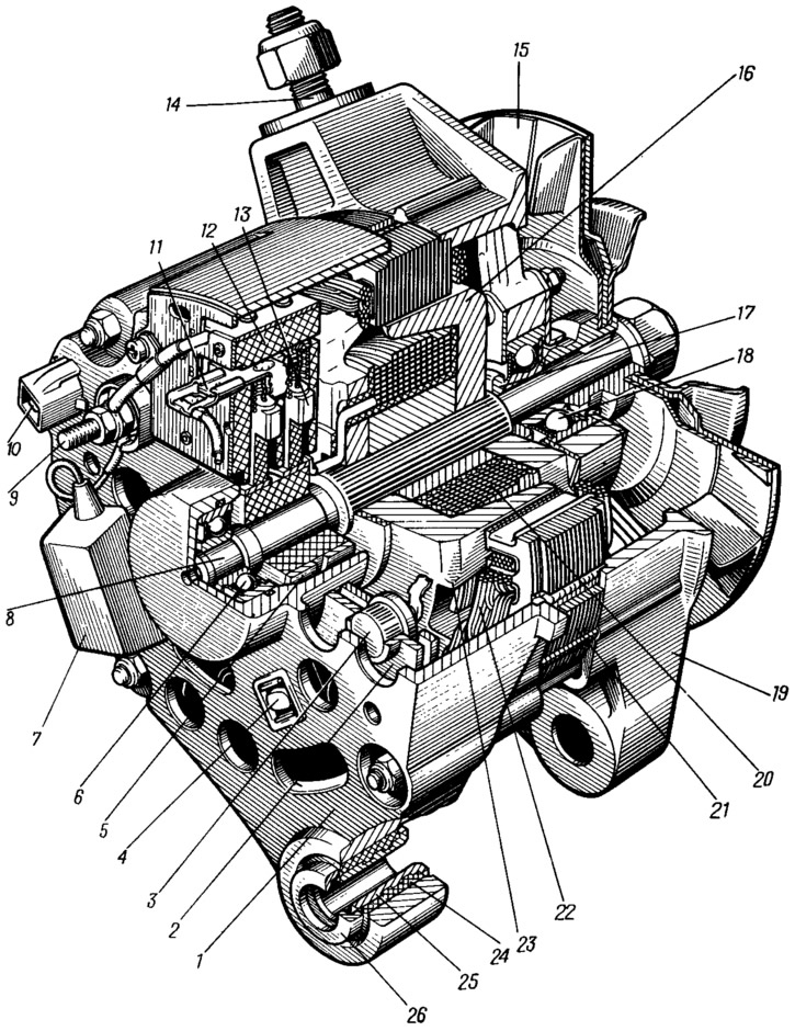
The generator is mounted on the engine on the left side (front, when viewed in the direction of the car) and is driven by a V-belt from the crankshaft pulley. With the paws of the covers, the generator is attached to the bracket on the engine, and with a pin 14 (pic. 97) - to the tension bar. To prevent the paws of the covers from breaking off when the fastening bolt is tightened, two steel bushings 25 and 26 and a rubber buffer bushing 24 are installed in the hole of the cover 1. When the bolt is tightened, the buffer bushing is compressed between the bushings 25, 26 and the axial tightening force is not transferred to the generator covers.

Pic. 97. Generator:
1 - cover from the side of slip rings; 2 - rectifier block; 3 - rectifier block valve; 4 - screw for fastening the rectifier unit; 5 - contact ring; 6 - rear ball bearing; 7 - capacitor; 8 - rotor shaft; 9 - output «30» generator; 10 - output «61» generator; 11 - output «IN» voltage regulator; 12 - voltage regulator; 13 - brush; 14 - stud fastening the generator to the tension bar; 15 - a pulley with a fan; 16 - pole tip of the rotor; 17 - remote bushing; 18 - front ball bearing; 19 - cover on the drive side; 20 - rotor winding; 21 - stator; 22 - stator winding; 23 - pole tip of the rotor; 24 - buffer sleeve; 25 - bushing; 26 - clamping sleeve.
The generator is assembled from the following units: rotor, stator 21, cover 1 on the side of the slip rings, cover 19 on the drive side, pulley 15 with a fan and brush holder with voltage regulator 12. The covers together with the stator are tightened with four coupling bolts.
Beak-shaped poles 16 and 23 and a steel sleeve are pressed onto the corrugated surface of the shaft 8 of the rotor, forming the magnetic system of the rotor. Between the poles in the plastic frame is the winding 20 of the rotor, called the excitation winding. The ends of the winding are brought out through holes in pole 23 and soldered to copper slip rings 5. A plastic sleeve with slip rings is also pressed onto the shaft.
The rotor rotates in two ball bearings 16 and 18. Closed-type bearings filled with a special lubricant during manufacture, sufficient for the entire life of the generator. The inner ring of the bearing 6 is pressed onto the rotor shaft, and the outer ring enters the seat of the cover / and is pressed with a rubber ring. The outer ring of the bearing 18 is pressed into the cover 19 and, for reliability, is additionally clamped between two steel washers tightened by four bolts. The inner ring of this bearing is loosely mounted on the rotor shaft and, together with the distance ring 17, is clamped between the pulley hub and the shaft shoulder with the pulley fastening nut.
The stator core 21 is made of plates of electrical steel, connected in four places by electric welding. On the inner surface of the stator there are 36 semi-closed slots, insulated with a fluoroplastic film. In the grooves, a three-phase stator winding is laid, connected to a star without a zero point output.
Covers 1 and 19 of the generator are cast from aluminum alloy and have ventilation windows for cooling the stator and rectifier windings with air. Air is sucked into the windows of the cover 1, passes between the stator and the rotor, and is thrown out through the windows of the cover 19 by the fan impeller. The parts of the pulley and the fan are made by stamping from sheet steel and connected by contact electric welding.
On the cover 1 of the generator, a screw is fixed to the assembly, consisting of a voltage regulator 12 and a brush holder. Through the brushes, pressed by springs to the contact rings of the rotor, current is supplied to the excitation winding. One of the brushes is connected to the output «IN» voltage regulator, and the other - with the output «W». The voltage regulator is microelectronic small-sized. It is a non-separable and non-adjustable unit and, in case of failure, is replaced by a new one.
Parts of the rectifier are also fixed on the cover 1 of the generator. The rectifier is assembled according to a three-phase bridge circuit of six silicon valves of the VA-20 type - semiconductor devices that pass current in only one direction. They are located in a special rectifier block 2, which consists of two aluminum plates with pressed-in valves. To simplify the design of the rectifier, three valves (positive) create on the body «plus» rectified current, and the other three (negative) — «minus» rectified current. Negative gates having a common terminal on «mass», are pressed into one plate of the rectifier unit, and positive - into another, connected to the clamp «30» generator. This terminal is the positive terminal of the rectifier and the negative terminal is «weight» generator.
The valves are press-fitted in order to ensure efficient heat dissipation from their body to the plates of the rectifier unit, which are blown through with air. The rectifier unit is attached to the cover 1 with three bolts 4, insulated together with the plate of positive valves from the cover from the cover with plastic bushings. The nuts of these bolts simultaneously clamp the terminals of the valves and the stator winding.
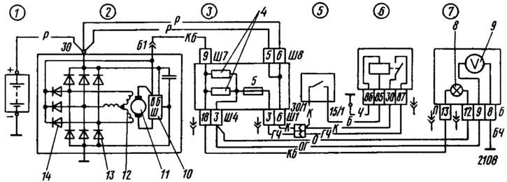
Three additional diodes are installed in the rectifier block 13 (see fig. 98). In combination with the negative valves of the rectifier unit, they form a separate rectifier, from which the excitation winding is fed when the generator is running. In addition, additional diodes allow you to apply a simple circuit for turning on the battery discharge warning lamp.

Pic. 98. Wiring diagram of the generator system:
1 - battery; 2 - generator; 3 - mounting block; 4 - additional resistors of 100 Ohm, 2 W; 5 - ignition switch; 6 - ignition relay; 7 - instrument cluster; 8 - control lamp of the battery discharge; 9 - voltmeter; 10 - voltage regulator; 11 - excitation winding; 12 - stator winding; 13 - rectifier unit valves; 14 - additional diodes.
To protect the electronic equipment of the car from voltage pulses in the on-board network, as well as to reduce interference with radio reception, a capacitor 7 is installed (see fig. 97) capacitance 2.2 uF.
The generator connection diagram is shown in fig. 98. The excitation winding of the generator is connected to the terminals «IN» and «W» voltage regulator. The voltage supplying the excitation winding is supplied to the output «IN» regulator from three additional diodes 14, and the voltage that controls the operation of the regulator - to the conclusion «B» from clamp «30» generator. The voltage created by the generator is fed from the stator winding to the rectifier and the already rectified one is removed from the clamp «30» generator.
