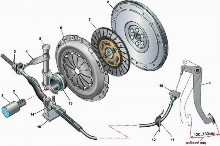
Clutch: 1 - release bearing guide sleeve; 2 - the input shaft of the gearbox; 3 - cable adjusting nuts; 4 - clutch release fork; 5 - fork axle bushing; 6 - pressure plate assembly (basket); 7 - driven disk; 8 - flywheel; 9 - clutch pedal; 10 - cable sheath bracket; 11 - anther; 12 - partition of the engine compartment; 13 - release bearing; 14 - nuts for fastening the cable sheath; 15 - bracket on the gearbox housing
The clutch is mounted on the flywheel and is covered by an aluminum crankcase that is bolted to the cylinder block. On the other hand, the clutch housing is connected to the gearbox housing.
On the splines of the input shaft of the gearbox, a driven disk is freely installed, divided by radial slots into twelve sectors. Friction linings made of a special material are riveted to the driven disk on both sides. The torque from the driven disk to its hub is transmitted through a spring-friction damper (vibration damper).
Leading part of the clutch (basket) attached to the flywheel with six bolts. The basket consists of a pressure plate, a casing and a diaphragm pressure spring. The pressure plate is movably fixed on elastic plates inside the casing. Under the action of a diaphragm spring, the driven disc is clamped between the pressure plate and the flywheel.
The upper tip of the cable is pivotally attached to the pedal. The lower tip of the cable is pivotally connected to the clutch release fork, the axis of which is mounted on two plastic bushings in the clutch housing. Release bearing - ball, angular contact. The release bearing clutch is put on the guide sleeve and is pressed against the clutch release fork by a spring.
The clutch is disengaged when the clutch pedal is depressed. When the fork is turned, the release bearing moves longitudinally along the guide sleeve.
The outer ring of the release bearing is constantly pressed against the petals of the diaphragm spring and rotates with it.
When the clutch is engaged, its driving and driven parts rotate as one, transferring torque from the engine crankshaft to the gearbox input shaft. When the clutch pedal is pressed, the clutch release fork, turning, moves the release bearing with its clutch along the guide sleeve. The bearing acts on the diaphragm spring, which, bending, takes the pressure plate away from the driven one and the transmission of torque is stopped. When the pedal is released, all parts of the clutch return to their original position under the action of the springs.
During operation, the lining of the driven disk wears out. As the clutch pedal wears, it rises off the floor and its travel increases. Therefore, when carrying out maintenance, it is necessary to check the condition of the clutch (see below, "Checking the technical condition of the clutch") and adjust pedal travel.
Clutch drive adjustment (pedal travel) is carried out by changing the position of the lower tip of the cable sheath in the bracket for its fastening.
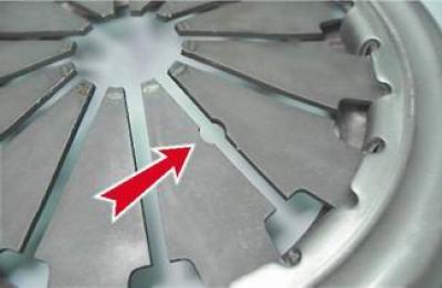
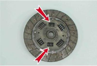
On vehicles with 16-valve engines (2112 and 21124) a clutch is installed that differs in the characteristics of the pressure spring of the leading part and the springs of the driven disc damper from the clutch used on vehicles with 8-valve engines (2111 and 21114).
Warning! Clutches on vehicles with 16-valve and 8-valve engines are not interchangeable.
You can distinguish the clutch of cars with 16-valve engines by the hole between the petals of the diaphragm spring...

...and two offset damper springs.

