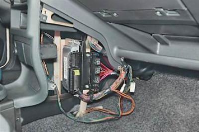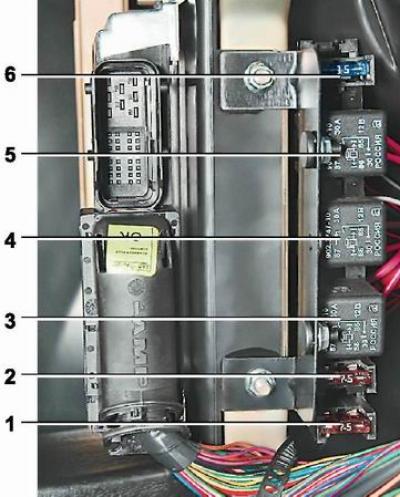
Location of the relay and fuses of the engine management system under the instrument panel console
Note. The right overlay of the console of the panel of devices is removed (see "Instrument panel - removal").

Relays and fuses for the engine management system: 1,2 and 6 - fuses (see table. 8.4.3); 3 - main relay; 4 - relay for turning on the electric fan of the engine cooling system; 5 - relay for turning on the fuel pump
Table 8.4.3. Engine management system fuses
| Position on the photo | Current strength, A | Protected circuits |
| 1 | 7,5* | Electronic control unit (ECU), ignition module |
| 2 | 7,5* | Coil of the relay for turning on the electric fan of the cooling system, the adsorber purge valve, the air flow sensor, the speed sensor, the oxygen concentration sensor |
| 6 | 15 | Fuel pump |
* On cars of the first years of production, fuses of 15 A were installed.
The fuse and relay mounting block has tweezers to remove the fuses (see "Fuse and relay mounting block").
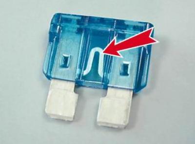
A bad fuse can be identified by a blown filament.

Recommendation: Sometimes the thread of the fuse remains intact, while its connection inside the fuse is broken. It is impossible to visually determine such a malfunction. In this case, you can evaluate the condition of the fuse using an ohmmeter.
Warning! Before replacing a fuse, the cause of the blown fuse must be determined and repaired. In order to avoid failure of the elements of the engine control system, fuses with an increased rating or home-made fuses should not be installed.
