1. Disconnect the wire from the terminal «–» battery.
2. Remove the alternator from the vehicle (see «Removal and installation of the generator»).
3. Mark the relative position of the generator covers.
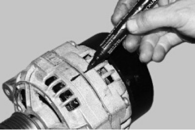
4. Release the three latches..
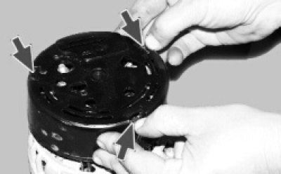
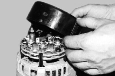
5.... and remove the plastic casing.
6. Turn out two screws of fastening of a voltage regulator.
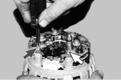
7. Remove the voltage regulator with brush holder..
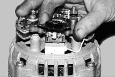
8.... and disconnect the block with the wire from the output of the regulator.
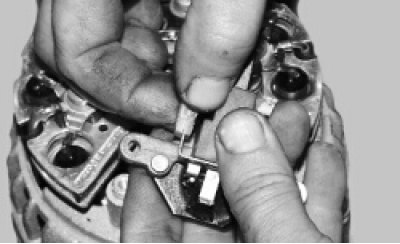
9. Turn out four screws of fastening of the rectifier block and the screw of fastening of the condenser.
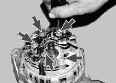
10. Unbend the three stator winding leads so that they make it possible to remove the rectifier unit.

11. Remove the rectifier unit with the capacitor.

12. To replace the capacitor, unscrew the nut of the contact bolt, remove the washer and spacer. Remove the condenser wire end cap from the terminal bolt.
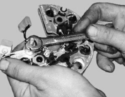
13. Remove the four pinch screws (screws are over tightened). Spring and flat washers are installed under the screw heads.
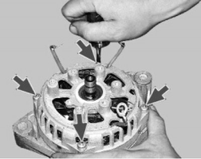
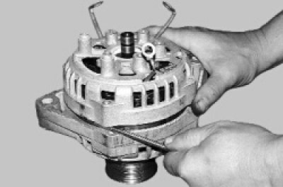
14. Using a screwdriver, remove the generator cover from the side of the slip rings.
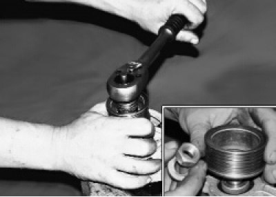
15. Clamp the generator rotor in a vise (not too much so that the rotor does not turn) and loosen the pulley nut. Remove spring washer and pulley.
16. Remove the thrust washer.
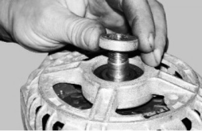
17. Remove the rotor from the cover on the drive side.
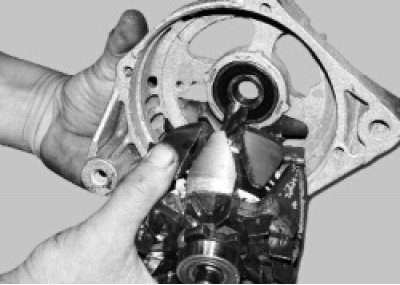
18. Remove the distance ring from the rotor shaft.
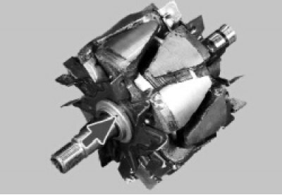
19. Examine contact rings. If they have scuff marks, marks, scratches, wear marks from brushes, etc., grind the rings. If damage to the rings cannot be removed with sandpaper, you can grind the rings on a lathe, removing the minimum layer of metal, and then grind.
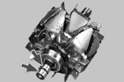
20. Check with an ohmmeter (tester) resistance of the rotor winding by connecting it to slip rings. If the ohmmeter shows infinity, then there is a break in the windings and the rotor needs to be replaced.

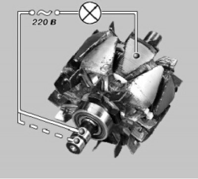
21. Check with a test lamp if there is a winding short circuit on the rotor housing. To do this, turn on the test lamp in a 220 V AC mains (can use rechargeable battery and 12V lamp). Connect one wire to the rotor housing, the second - in turn to each ring. In both cases, the lamp should not light. If at least in one case the lamp is on, then a short circuit occurs and the rotor must be replaced.
22. Remove the stator from the front cover housing. On the inner surface of the stator there should be no traces of armature touching the stator. If there is wear, the bearings or alternator covers must be replaced.
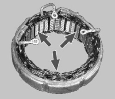
23. Check for an open in the stator winding. To do this, turn on the test lamp in a 220 V AC mains (can use rechargeable battery and 12V lamp). Alternately connect a test lamp between all terminals of the winding. In all three cases, the lamp should be on. If the lamp does not light up, there is a break in the winding. Replace stator or winding.

24. Check if there is a short circuit in the stator windings to the housing. To do this, turn on the test lamp in a 220 V AC mains (can use rechargeable battery and 12V lamp). Connect the lamp to the stator winding terminal, and the wire from the current source to the stator housing. If the lamp lights up, then there is a short circuit and it is necessary to replace the stator or winding.

25. Examine a cover of the generator from a drive end in gathering with the bearing. If during rotation of the bearing you feel play between the rings, rolling or jamming, the protective rings are damaged or there are traces of lubricant leakage, cracks are found in the cover, especially in the places where the generator is attached, it is necessary to replace the cover assembly with the bearing (the bearing in the cap is rolled).
26. Check up ease of rotation of the bearing from slip rings. If during rotation of the bearing there is play between the rings, rolling or jamming, the protective rings are damaged or there are traces of grease leakage, the bearing must be replaced. To do this, use a puller to press the bearing off the rotor shaft and press on a new one using a suitable mandrel, applying force to the inner ring of the bearing.
27. Inspect the generator cover from the side of the slip rings. If cracks are found, the cover must be replaced.
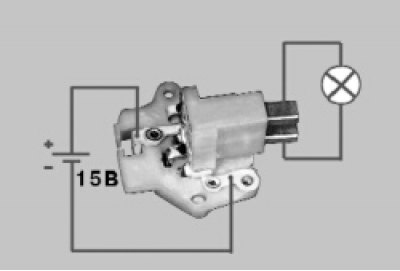
28. Check the voltage regulator. Connect a 12 V test lamp to the brushes. Apply 12V voltage: «+» on the clamp «–» on «mass» brush holder. The control lamp should light up.
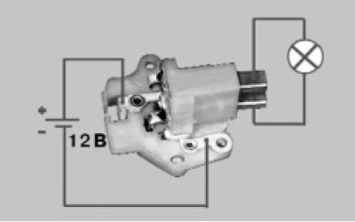
29. Increase the voltage to 15-16 V - the lamp should go out. If the lamp does not go out or does not light up at 12 V, replace the regulator with brush holder.
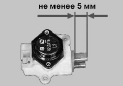
30. Check the ease of movement of the brushes in the brush holder and their protrusion. If the brushes protrude from the brush holder by less than 5 mm, replace the voltage regulator with the brush holder. If chips or cracks are found on the brushes, replace the regulator.
31. The health of the capacitor can be checked with a megger or tester (on a scale of 1–10 MΩ). Connect the tester probes to the capacitor terminals. Before connecting, the device shows infinity. At the moment of connection, the resistance decreases, and then returns again to infinity. In this case, the capacitor is good. A defective capacitor must be replaced.
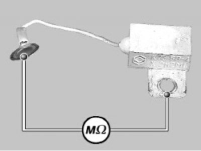
32. You can check the rectifier unit both on the removed generator and without removing the generator from the car. The check procedure is the same. For clarity, the test circuits are shown on the removed generator. To test on the vehicle, disconnect the wires from the battery and alternator. Remove the wire block from the output of the voltage regulator, unscrew the two screws and remove the brush holder from the generator.
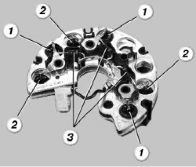
1 - positive diodes (with a red mark on the body); 2 - negative diodes (with black mark on the body); 3 - additional diodes.
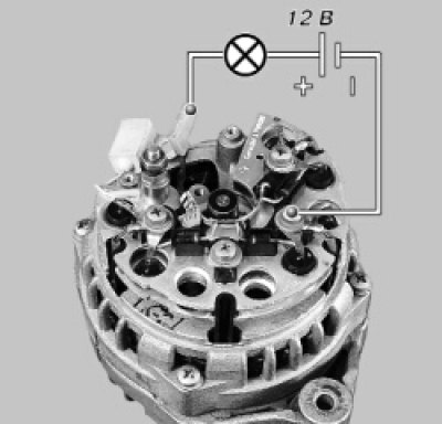
33. Check the diodes of the rectifier unit using a 12 V test lamp and a battery. To test for shorts in the positive and negative diodes, connect «+» batteries through the control lamp to the output «B+» generator, and «–» batteries - to the generator housing. The lamp should not light up. If the lamp is on, then there is a short circuit. The block needs to be replaced.
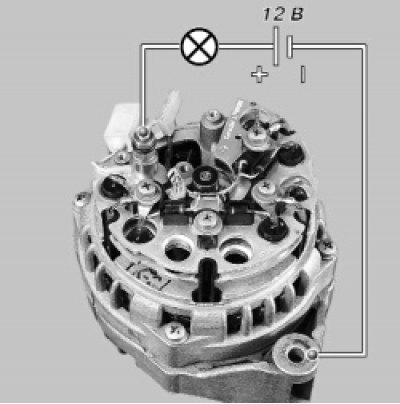
34. To test positive diodes, connect «+» battery through the control lamp to the output «B+» generator, and the wire coming from «–» battery, - to one of the screws securing the stator winding output. The lamp should not light up. If it is on, then there is a short circuit in the positive diodes. The block needs to be replaced.
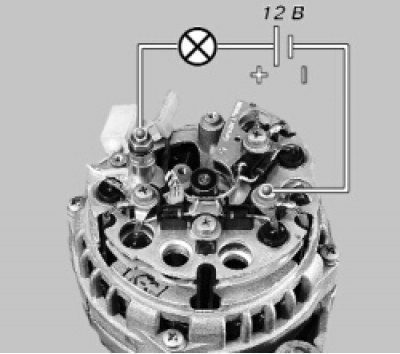
35. To test negative diodes, connect «+» battery through a test lamp to one of the screws securing the stator winding output, and the wire coming from «–» battery, - to the generator housing. The lamp should not light up. If the lamp is on, then there is a short circuit in the negative diodes. The block needs to be replaced.
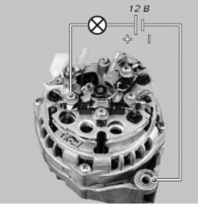
36. To test additional diodes, connect «+» battery through a test lamp to the contact of the voltage regulator connector block, and the wire coming from «–» battery, - to one of the screws securing the stator winding output. The lamp should not light up. If the lamp is on, then there is a short circuit in the additional diodes. The block needs to be replaced.
37. Assemble the generator in the reverse order of disassembly. Orient the generator cover according to the previously made marks. Install the spring washer of the alternator pulley with the convex side to the nut. Tighten the nut to a torque of 39–62 Nm (3.9–6.2 kgf·m).
Note. When assembling, the capacitor must be precisely oriented relative to the mounting protrusion on the cover, otherwise the brush holder will not fit into place.
