Movement mechanism
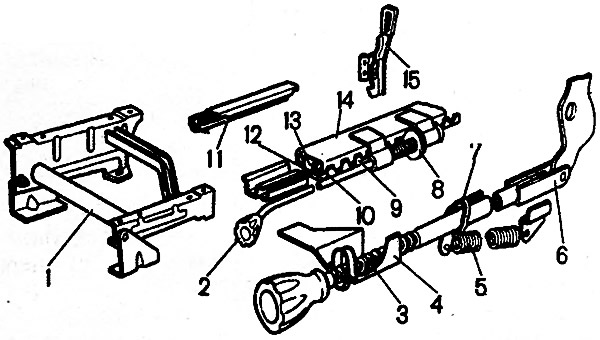
Bend the edges of the sliders 14 (pic. 8-31) and slide guides 12, remove all balls 10 and slide the guides relative to the sliders until the rollers 13 exit.

Pic. 8-31. Front seat adjustment mechanisms: 1 - skeleton of the front seat; 2 - handle of the movement mechanism, 3 - screw rod of the backrest tilt adjustment mechanism; 4 - backrest tilt lock, 5 - spring; 6 - thrust; 7 - cotter pin; 8 - latch of the movement mechanism; 9 - lock of the movement mechanism, 10 - ball; 11 - seat slide; 12 - slide guide; 13 - roller; 14 - slide slider; 15 - seat latch
To assemble, insert the rollers into the grooves of the slider and slide the guide. Then insert the balls and bend the rims.
Backrest adjustment mechanism
Disconnect the spring 5 from the rod and knock out the pin connecting the rod 6 to the seatback reinforcement. Remove the cotter pin and remove the rod from the latch 4 of the backrest tilt mechanism.
Assemble the mechanism in reverse order.
