- Rated voltage, V - 12
- Rated power, kW - 1.3
- Current consumption at maximum power, no more than, A - 260
- Consumed current in the inhibited state, no more than, A - 500
- Current consumption at idle, no more than, A - 35 (60*)
* For starter 35.3708
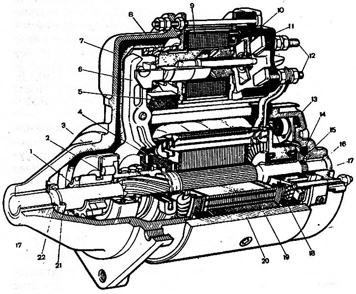
The starter device is shown in fig. 7-13, and the connection diagram in fig. 7-14. The diagram shows a starter with two windings in a traction relay, which has been installed on parts of cars since 1983. Until 1983, only a starter with a single-winding traction relay was used. Since 1986, a starter type 35.3708 has been installed on some cars, which has an end collector, as well as three serial stator windings and one shunt winding.

Pic. 7-13. Starter St-221: 1 - drive gear; 2 - overrunning clutch roller; 3 - overrunning clutch; 4 - driving ring; 5 - rubber plug; 6 - drive lever; 7 - starter cover on the drive side; 8 - relay armature; 9 - relay winding; 10 - contact plate; 11 - relay cover; 12 - contact bolts; 13 - cover from the side of the collector; 14 - brake disc cover; 15 - brake disc of the armature shaft; 16 - anchor; 17 - bearing sleeve; 18 - stator winding; 19 - stator pole; 20 - starter housing; 21 - restrictive ring; 22 - adjusting ring

Pic. 7-14. Starter connection diagram: 1 - starter; 2 - ignition switch; 3 - generator; 4 - battery
