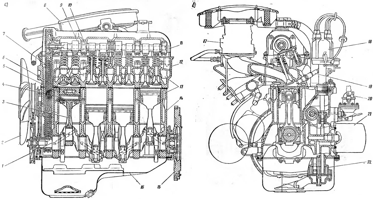
car engine «Niva» (pic. 2) piston, internal combustion, carburetor, four-stroke, model 2121. It has four cylinders arranged in one row and an overhead valve arrangement. The combustible mixture is prepared outside the cylinders (in the carburetor) and ignites inside them with an electric spark. The working cycle of the engine takes four cycles (intake, compression, stroke, exhaust), and the gases expanding during the combustion of the mixture move the pistons in the cylinders, the reciprocating motion of which is converted into the rotational motion of the crankshaft. The order of operation of the engine cylinders (alternation of working strokes in cylinders) 1—3—4—2.

Open large image in new tab »
Pic. 2. Engine: a - longitudinal section; b - cross section:
1 - crankshaft; 2 - fan; 3 - connecting rod; 4 - piston pin; 5 - piston ring; 6 - piston; 7 - camshaft drive circuit in the oil pump; 8 - air filter; 9 - camshaft: 10 - valve; 11 - cylinder head cover; 12 - cylinder head; 13 - cooling jacket; 14 - cylinder block; 15 - flywheel; 16 - oil pan; 17 - carburetor: 18 - ignition distributor; 19 - spark plug; 20 - fuel pump; 21 - oil filter; 22 - oil pump.
1 - crankshaft; 2 - fan; 3 - connecting rod; 4 - piston pin; 5 - piston ring; 6 - piston; 7 - camshaft drive circuit in the oil pump; 8 - air filter; 9 - camshaft: 10 - valve; 11 - cylinder head cover; 12 - cylinder head; 13 - cooling jacket; 14 - cylinder block; 15 - flywheel; 16 - oil pan; 17 - carburetor: 18 - ignition distributor; 19 - spark plug; 20 - fuel pump; 21 - oil filter; 22 - oil pump.
The engine consists of crank and gas distribution mechanisms of cooling, lubrication, power supply and ignition systems.
Crank mechanism
The crank mechanism is designed to convert the reciprocating motion of the pistons into the rotational motion of the crankshaft. It consists of moving and fixed parts. The fixed parts are (see fig. 2): cylinder block 14, cylinder head 12 and crankcase. To moving parts - pistons 6, piston rings 5, piston pins 4, connecting rods 3, crankshaft I and flywheel 15. Pistons, piston rings and piston pins as an assembly form a piston group.
Cylinder block is the backbone of the engine. Engine mechanisms and devices are placed on it and inside it. It is a group of cylinders made in a common casting with the upper part of the crankcase from special low-alloy cast iron. Inside the block between the walls of the cylinders and its outer walls there is a special cavity called the cooling jacket. It circulates the coolant of the engine cooling system. At the bottom of the cylinder block are supports (post-, whether) for main bearings of the crankshaft of the engine. To increase rigidity, the lower plane of the cylinder block is somewhat lowered (by 50 mm) relative to the axis of the crankshaft.
cylinder head closes the cylinders from above and serves to accommodate wedge-shaped combustion chambers and gas distribution mechanics parts in it, the cylinder head is made common to all cylinders and is cast from aluminum alloy. It has channels for the inlet of a combustible mixture and the outlet of exhaust gases, a cooling jacket and threaded holes for spark plugs. Seats and valve guides made of cast iron are pressed into the head. The head is bolted to the cylinder block. A metal-asbestos gasket is installed between the head and the cylinder block, which ensures the tightness of their connection. From above, a bearing housing with a camshaft is attached to the cylinder head with studs, and it is closed with a cover, under which a sealing gasket is installed.
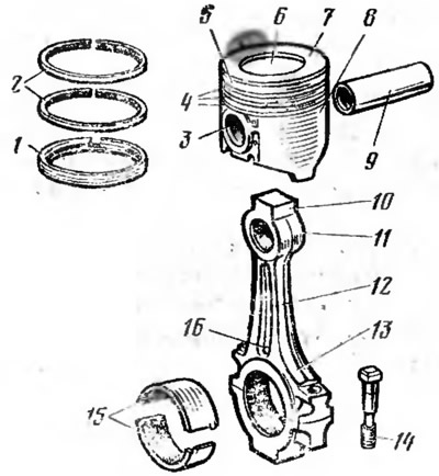
Piston (pic. 3) serves to perceive the pressure of gases during the working stroke and the implementation of auxiliary cycles (intake, compression, exhaust). Piston 7 is a hollow cylinder cast from aluminum alloy. It has a flat bottom 6, a head 5 and a skirt 8. The bottom of the piston bottom is reinforced with ribs. Grooves 4 for piston rings are made in the piston head. There are 3 tides in the skirt (bosses) with holes for the piston pin. The skirt is oval in cross section, conical in height and cut out at the bottom. The ovality and taper of the skirt prevent the piston from jamming in the cylinder, and the cutouts prevent the piston from touching the counterweights of the crankshaft. In addition, cutouts in the skirt reduce the mass of the piston. For better running-in to the cylinders, the outer surface of the piston skirt is coated with a thin layer of tin. The hole in the bosses for the piston pin is offset relative to the diametral plane of the piston (by 2 mm). This reduces the distortion and impact of the piston when it passes through the top dead center!

cis. 3. Piston group and engine connecting rod:
1 - oil scraper ring; 2 - compression ring: 3 - boss; 4 - grooves; 5 - head; 6 - bottom; 7 - piston. 8 - skirt; 9 - piston pin; 10 - connecting rod; 11 - upper head; 12 - rod; 13 - lower head; 14 - bolt; 15 - bearing shell; 16 - lubrication hole.
Piston rings seal the cylinder cavity, exclude the breakthrough of gases into the crankcase (compression 2) and oil entering the combustion chamber (oil scraper I). In addition, they remove heat from the piston head to the cylinder walls. Compression and oil scraper rings are split. They are made from a special cast iron. Due to their elasticity, they fit snugly against the walls of the cylinder, while between the cut ends of the rings (in castles) a small gap remains (0.2—0.35 mm).
piston pin serves to articulate the piston on the upper head of the connecting rod. It is tubular, steel, pressed into the upper head of the connecting rod with an interference fit and rotates freely in the piston bosses.
connecting rod serves to connect the piston to the crankshaft and transfer forces between them. It is steel, forged and consists of a one-piece upper head 11, an I-section rod 12 and a split lower head 13. The connecting rod is connected to the crankshaft by the lower head. The removable half of the lower head is the connecting rod cap and is bolted to it. Thin-walled bimetallic, steel-aluminum liners 15 of the connecting rod bearing are inserted into the lower head of the connecting rod. In the lower head of the connecting rod there is a special hole 16 for lubricating the cylinder walls.
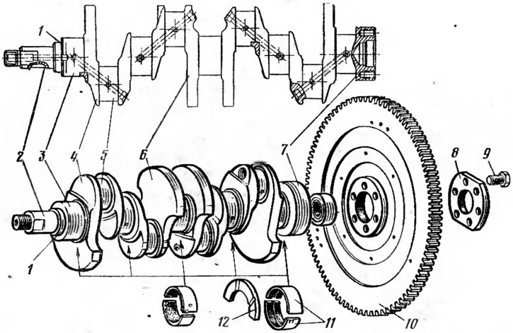
Crankshaft (pic. 4) perceives the efforts from the connecting rods and transmits the torque generated on it to the vehicle's transmission. It also powers various engine mechanisms (gas distribution mechanism, oil pump, water pump, etc.). The crankshaft is five-bearing, cast from special high-strength cast iron. It consists of main 3 and connecting rod 5 necks, cheeks 4, counterweights 6, front 2 and rear 7 ends. The main journals of the crankshaft are mounted in bearings (main supports) engine crankcase, liners 11 of which are thin-walled bimetallic, steel-aluminum. The lower connecting rod heads are attached to the connecting rod journals of the crankshaft. The connecting rod bearings are lubricated through the channels connecting the main journals with the connecting rod bearings. The cheeks connect the main and connecting rod journals of the crankshaft, and the counterweights unload the main bearings from the centrifugal forces of unbalanced masses. At the front end of the crankshaft, a timing chain drive sprocket, a belt drive pulley for driving a fan, a coolant pump, a generator and a ratchet for turning the shaft manually are mounted. At the rear end of the crankshaft there is a special socket for installing the gearbox input shaft bearing. A flywheel 10 is bolted to the end of the rear end of the shaft with the help of a special washer 8. From axial movements, the crankshaft is fixed by two thrust half rings 12, which are installed in the engine cylinder block on both sides of the rear main bearing. Moreover, a steel-aluminum semi-ring is placed on the front side of the bearing, and a metal-ceramic one on the back.

Pic. 4. Crankshaft and engine flywheel:
1 - crankshaft; 2 - front end; 3 - root neck; 4 - cheek; 5 - connecting rod neck; 6 - counterweight; 7 - rear end; 8 - washer; 9 - bolt; 10 - flywheel; 11 - bearing shell; 12 - persistent half ring.
Flywheel ensures uniform rotation of the crankshaft, accumulates energy during the working stroke to rotate the shaft during preparatory cycles and removes the parts of the crank mechanism from dead points. The energy stored in the flywheel makes it easier to start the engine and ensure the car starts off. The flywheel is a massive disk cast from cast iron. A steel ring gear is pressed onto the flywheel rim, designed to start the engine with an electric starter. Clutch parts are attached to the flywheel.
Engine mount. The engine assembly with clutch and gearbox is installed on the car on three elastic supports (two front and one back). Elastic mounts reduce engine vibrations and soften shocks transmitted to the engine from road bumps while driving. The front supports of the engine are attached to the cross member of the front suspension of the car, and the rear support - to the cross member of the rear engine suspension. The front supports have elastic elements, which are rubber cushions, in which steel washers with fastening bolts are vulcanized. At the rear support, the rubber cushion is vulcanized in a steel cage and has a steel bushing.
