The lubrication system of the car engine is combined - under pressure and spray. Under pressure, the most loaded friction parts are lubricated: main and connecting rod bearings of the crankshaft, camshaft thrust bearings and oil pump drive shaft bearings. Cylinder walls, pistons, piston rings, piston pins, parts of the gas distribution mechanism, its drive and other parts are lubricated by spraying.
Oils used for the engine: summer M-12G1, M-12GI; winter M-8G1, M-8GI; all-weather M-6310G1, M-10GI.
The lubrication system includes: oil sump, oil pump with pressure reducing valve and oil receiver, oil filter, oil lines (channels in the cylinder head and block, crankshaft and camshaft), filler neck and oil level indicator.

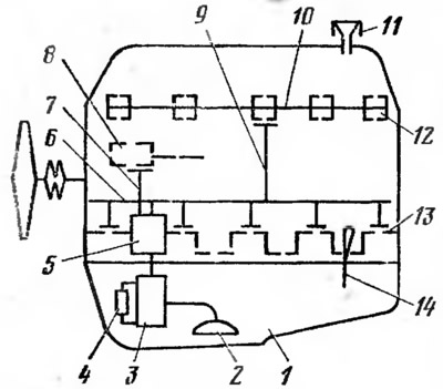
Pic. 6. Schematic diagram of the engine lubrication system:
1 - oil pan: 2 - oil dispenser; 3 - oil pump; 4 - pressure reducing valve; 5 - oil filter: 6 - oil line; 7 - oil channels; 8 - pump drive roller; 10 - central camshaft valve; 11 - filler neck; 12 - camshaft. 13 - crankshaft; 14 - oil measuring rod.
Schematic diagram of a car engine lubrication system «Niva» VAZ-2121 is shown in fig. 6. Oil is poured into the pan 1 through the neck 11, its amount is controlled by a special rod 14, the end of which is in the oil bath. When the engine is running, oil is taken from the sump by pump 3 through oil receiver 2 and is fed through the intake channel in the cylinder block to filter 5, which is connected in series to oil line 6. From the filter, oil through line 6 and channel 7 in the cylinder block under pressure enter, respectively, the main bearings of the crankshaft 13 and the bearing of the oil pump drive shaft 8. The maximum oil pressure generated by the pump is limited by the pressure reducing valve 4 installed in the oil pump. When filter 5 is clogged, oil also enters the oil line, bypassing the filter, through the bypass valve, which is installed in the filter. From the main bearings, oil is supplied through the internal channels of the crankshaft to the connecting rod bearings and from them through the holes in the lower heads of the connecting rods it is sprayed onto the cylinder walls. Piston rings and piston pins are lubricated by oil skimmed from the cylinder walls and oil mist inside the engine. To the central support bearing of the camshaft 12, oil from the pressure filter enters through line 6 and channel 9. The oil that enters through the groove in the support enters the central channel 10 of the camshaft and from it to other support bearings and shaft cams. The camshaft drive sprocket and chain are lubricated by oil flowing from the front shaft support bearing. Valve stems, guide bushings and other valve parts are lubricated with oil sprayed by engine mechanisms during their operation. The used oil flows into the oil pan. The oil pressure in the system is controlled by an electric pressure gauge and a control lamp, the sensors of which are installed on the engine block.
oil pan (see fig. 2) is the oil reservoir. It closes the engine from below, and the oil is cooled in it. The oil pallet steel, stamped. Inside the sump there are vertical and horizontal partitions that reduce oil fluctuations when the car is moving. The pallet is attached to the lower end of the cylinder block (to crankcase) through the seal. It has a threaded hole with a plug for draining oil.
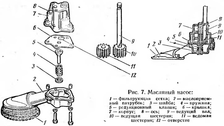
Oil pump (pic. 7) supplies oil under pressure to rubbing surfaces. Oil pump gear type, single section. An oil inlet pipe is attached to the pump housing 7 through the cover 6. 2 with a filter mesh 1 and a pressure reducing valve 5. The drive gear 10 is pressed onto the drive shaft 9 of the pump. Driven gear 11 rotates freely on an axle pressed into the oil pump housing. When the gears rotate, a vacuum is created, and the oil through the filter mesh and the pipe enters under the cover 6 of the pump and through the hole 12 in the cover into the vacuum cavity of the pump housing. The oil filling the cavities between the gear teeth is transferred to the discharge cavity, and from there it enters the intake channel of the engine block. With an increase in oil pressure in the lubrication system of more than 4.5 kgf / cm2 (0.45 MPa) the pressure reducing valve 5 opens, bypassing part of the oil from the discharge cavity into the oil intake pipe 2, and the pressure in the system does not increase. The pump drive shaft is driven by a gear from the oil pump drive shaft, which is driven by a chain drive from the engine crankshaft.

Pic. 7. Oil pump:
1 - filter mesh; 2 - oil inlet pipe: 3 - washer; 4 - spring; 5 - pressure reducing valve; 6 - cover; 7 - body; 8 - axis; 9 - drive shaft; 10 - drive gear; 11 - driven gear; 12 - hole.
Oil filter cleans oil from solid particles (wear products of rubbing parts, carbon deposits, etc.), since they call. increased wear of parts and clog oil lines. Oil filter full flow (passes everything that is injected. oil), non-separable with a bypass valve. Its filter element is paper with a special viscose fiber insert. The oil pumped by the pump enters the filter, passes through the pores of the filter element, is cleaned in it and exits into the oil line of the cylinder block. The filter element insert cleans the oil when starting a cold engine when it cannot pass through the paper filter element. With severe filter contamination, as well as with increased oil viscosity (at low temperatures) the bypass valve of the oil filter opens, and the crude oil from the filter enters the oil line.
crankcase ventilation The engine serves to remove crankcase gases, which consist of a combustible mixture and combustion products, dilute the oil and form resinous substances and acids in it. In addition, they increase the pressure in the crankcase and cause oil to leak through the seals.
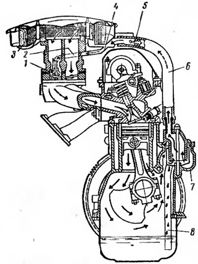
Engine ventilation system (pic. 8) closed type. It provides, due to the rarefaction in the intake pipeline, the forced removal of crankcase gases into the engine cylinders for afterburning. When the engine is running, crankcase gases are sucked out through the oil separator 7 and hose 6 into the exhaust manifold 4 of the air filter 3. From the exhaust manifold at idle and low engine loads, the gases enter through the hose 2 and spool 1 under the carburetor throttle. In other engine operating modes, crankcase gases enter the carburetor through the air filter. In the oil separator 7, oil is released from the gases, which flows through the tube 8 into the oil pan. Flame arrester 5 eliminates the penetration of flame into the crankcase during flashes in the carburetor.

Pic. 8. Engine crankcase ventilation system:
1 - spool; 2 - gas outlet hose; 3 - air filter; 4 - exhaust manifold 5 - flame arrester; 6 - gas suction hose; 7 - oil separator; 8 - oil separator tube.
