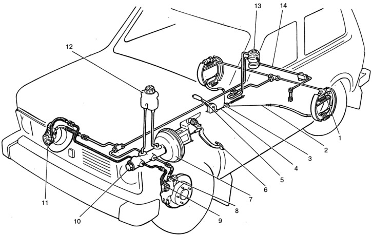
Pic. 6-1. Brake system diagram:
1 - rear brake wheel cylinder; 2 - rear parking brake cable; 3 - rear cable guide; 4 - front parking brake cable; 5 - parking brake lever; 6 - brake pedal; 7 - vacuum amplifier; 8 - pipeline of the secondary circuit; 9 - pipeline of the primary circuit; 10 - main cylinder; 11 - block of wheel cylinders of the front brake; 12 - tank of the main cylinder; 13 - pressure regulator; 14 - pressure regulator drive lever.
