Open large image in new tab »
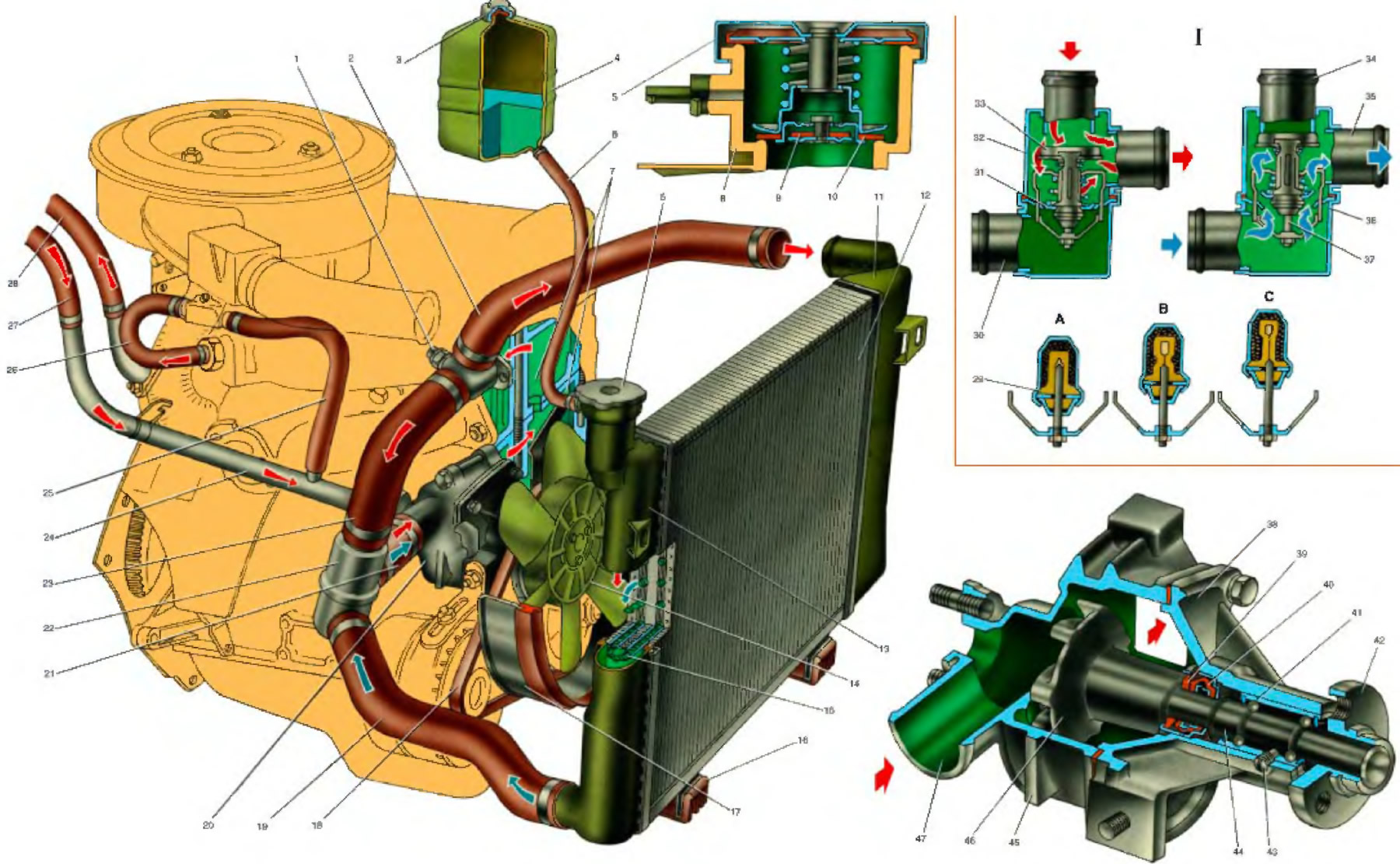
1. Coolant temperature sensor for fuel injection system; 2. Radiator inlet hose; 3. Tank stopper; 4. Expansion tank; 5. Radiator plug; 6. Fluid outlet hose to the expansion tank; 7. Cooling jacket; 8. Filler neck; 9. Inlet valve plugs; 10 Graduation (steam) stopper valve; 11. Left radiator tank; 12. Radiator core; 13. Right radiator tank; 14. Fan impeller; 15. Turbulator; 16.Rubber support radiator; 17. Fan cover; 18. Fan belt; 19. Outlet radiator hose; 20. Coolant pump; 21. Coolant supply hose to the pump; 22. Thermostat; 23. Thermostat bypass hose; 24. Pipe for draining fluid from the heater radiator; 25. Hose for draining fluid from the carburetor heating unit; 26. Hose for supplying fluid to the carburetor heating unit; 27. Hose for draining fluid from the heater radiator; 28. Hose for supplying liquid to the heater radiator; 29. Rubber insert; 30. Inlet pipe (from the radiator); 31. Main valve; 32. Thermostat housing; 33. Bypass valve; 34. Branch pipe of the bypass hose; 35. Pipe for supplying coolant to the pump; 36. Thermostat cover; 37. Piston; 38. Pump cover; 39. Thrust sealing ring gland; 40. Gland seal; 41. The outer ring of the pump roller bearing; 42. Fan pulley hub; 43. Locking screw; 44. Pump roller; 45. Pump housing; 46. Pump impeller; 47. Receiving pipe.
I. Scheme of thermostat operation; A. Liquid temperature less than 80°C; B. Fluid temperature 80 to 94°C; C. Fluid temperature over 94°C.
I. Scheme of thermostat operation; A. Liquid temperature less than 80°C; B. Fluid temperature 80 to 94°C; C. Fluid temperature over 94°C.
