Remove the carburetor by disconnecting the hoses and throttle linkage from it.
Remove the fuel pump and ignition distributor. Using the key 67.7812.9514, unscrew the spark plugs and coolant temperature indicator sensor.
Remove the alternator drive belt and coolant pump, remove the alternator and alternator bracket.
Remove the coolant pump by disconnecting the coolant supply pipe from the heater from the pump and exhaust manifold.
Remove the coolant outlet pipe and the coolant outlet pipe to the heater from the cylinder head.
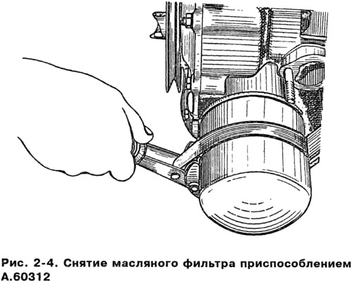
Using tool A.60312, unscrew and remove the oil filter with gasket (pic. 2-4).
Turn out the gauge of a control lamp of pressure of oil.
Remove the crankcase breather cap, crankcase and oil pump. Remove the oil separator drain tube retainer and remove the crankcase ventilation oil separator.
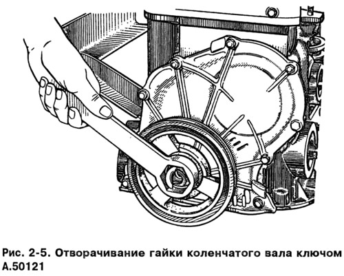
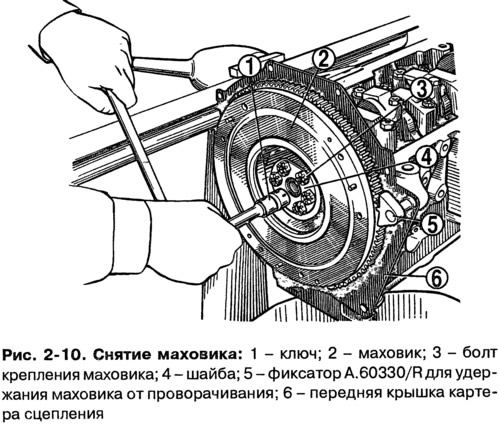
Remove the crankshaft pulley by securing the flywheel with lock A.60330/R (pic. 2-10) and unscrewing the key A,50121 nut (pic. 2-5).
Remove the cylinder head cover and camshaft chain cover. Loosen the camshaft sprocket and oil pump drive shaft bolts.
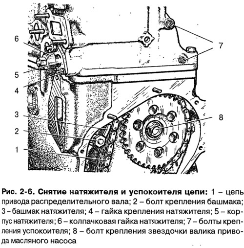
Loosen cap nut 6 (pic. 2-6) chain tensioner, unscrew the nuts 4 securing it to the cylinder head, remove the tensioner and, unscrewing the bolt 2, remove the shoe 1 of the chain tensioner.
Unscrew the chain stop pin, remove the oil pump and camshaft drive sprockets and remove the chain.
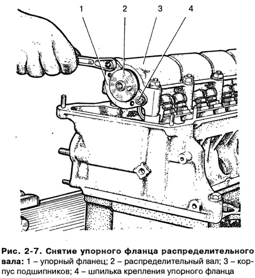
Loosen the stud nuts 4 (pic. 2-7). Remove the camshaft bearing housing. Having unscrewed the nuts of the studs 4 and, having removed the thrust flange 1, carefully, so as not to damage the surface of the bearing housing supports, remove the camshaft.
Turn away bolts of fastening of a head of cylinders and remove it together with an exhaust manifold and an inlet pipe.
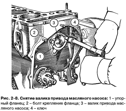
Remove thrust flange 1 (pic. 2-8) oil pump drive roller and remove the roller from the cylinder block.
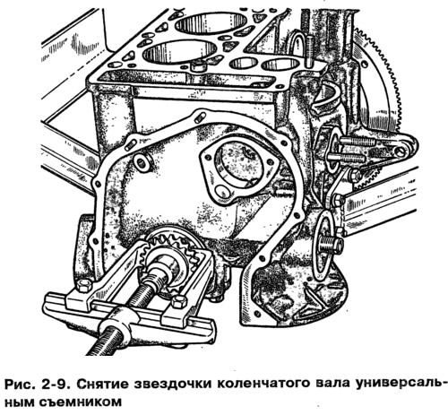
Using a universal puller A.40005/1/7 from the set A40005, remove the sprocket from the crankshaft (pic. 2-9).
Unscrew the nuts of the connecting rod bolts, remove the connecting rod caps and carefully remove the pistons with connecting rods through the cylinders. Mark the piston, connecting rod, main and connecting rod bearing shells in order to install them in their original place during assembly.
Warning When removing the connecting rod and piston group, it is not allowed to press out the connecting rod bolts from the connecting rods.
Install retainer 5 (pic. 2-10), unscrew the bolts 3, remove the washer 4 and the flywheel from the crankshaft. Remove the front clutch housing cover.
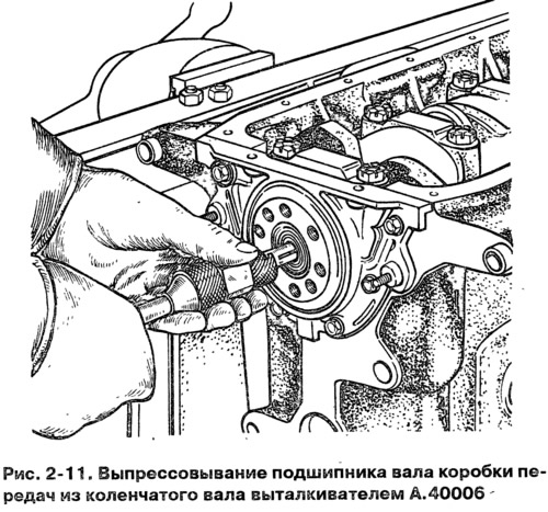
Using A.40006 ejector, remove the bearing of the input shaft of the gearbox from the socket in the crankshaft (pic. 2-11).
Remove the crankshaft oil seal holder.
Turn away bolts of covers of radical bearings, remove them together with the bottom loose leaves, remove a cranked shaft, top loose leaves and persistent half rings on a back support.
