Install a clean block on the stand and wrap the missing studs in it.
Lubricate the bearing shells and thrust washers of the crankshaft, as well as the pistons and oil seals, with engine oil. When assembling the engine after repair, install new crankshaft oil seals.
Lay loose leaves without a groove on the inner surface in the middle bearing seat and in its cover. Place liners with a groove in the remaining nests of the cylinder block, and liners without a groove in the corresponding covers.
Lay the crankshaft in the main bearings and insert two thrust half rings into the sockets of the rear support (pic. 2-12).
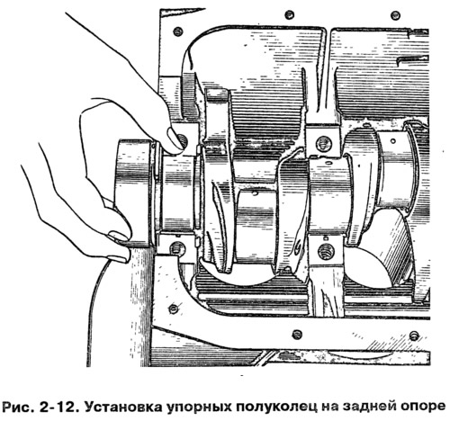
Warning: Half rings must face the grooves towards the thrust surfaces of the crankshaft (on the side of the grooves, an anti-friction layer is applied to the surface of the half-ring). On the front side of the rear support, place a steel-aluminum half ring, and on the back side, a cermet (yellow color).
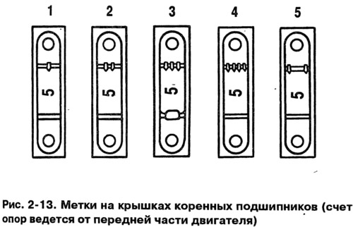
Install the main bearing caps in accordance with the marks on their outer surface (pic. 2-13). Tighten the cap screws.
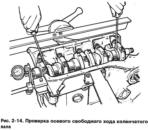
Check the axial free play of the crankshaft. To do this, place the indicator on a magnetic stand and insert the ends of two screwdrivers as shown in fig. 2-14. While moving the shaft with screwdrivers, measure the axial free play of the shaft with an indicator. It should be within 0.06-0.26 mm. If the free play is greater, then bring it back to normal by replacing the old half rings with new ones or by installing half rings of increased thickness.
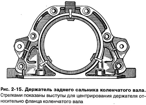
Put on the flange of the crankshaft the gasket of the rear oil seal holder, and in the sockets of the holder (pic. 2-15) insert the clutch housing front cover bolts. Put the holder with the stuffing box on the mandrel 41.7853.4011 and, moving it from the mandrel to the crankshaft flange, attach it to the cylinder block.
Install on two centering sleeves (pic. 2-16) front cover 6 (rice. 2-10) clutch housing. Attach the cover with nuts to the rear oil seal holder.
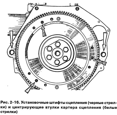
Install the flywheel on the crankshaft so that the mark (cone-shaped hole) near the rim was against the axis of the crankpin of the fourth cylinder, lock the flywheel with lock A.60330/R and bolt it to the crankshaft flange.
Using bushing 67.8125.9502 for crimping piston rings, insert pistons with connecting rods into the cylinders (pic. 2-17).
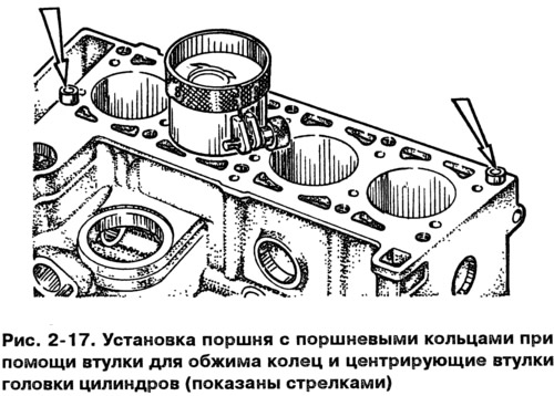
Warning: The pin hole on the piston is off-axis by 1.2 mm, therefore, when installing the pistons in the cylinders, the arrow on the piston crown must point towards the camshaft drive.
Install the bearings in the connecting rods and connecting rod caps. Install the connecting rods and caps on the crankshaft journals and tighten the connecting rod bolts. Connecting rod caps must be installed so that the cylinder number on the cap is opposite the cylinder number on the bottom end of the connecting rod.
Install the sprocket on the crankshaft. Install the oil pump drive shaft and secure with the thrust flange.
Insert two centering bushes into the cylinder block (pic. 2-17) and install the cylinder head gasket over them.
Warning: When assembling the engine, always install a new gasket under the cylinder head. The use of a used gasket is not permitted. Before installing the gasket, all oil must be removed from the mating surfaces of the block and cylinder head. The gasket must be clean and dry. Oil must not be allowed to come into contact with the gasket surface. If oil gets in, degrease the gasket.
Turn the crankshaft so that the pistons are in the middle of the cylinders.
Install the cylinder head assembly with valves, exhaust manifold and intake pipe along the two centering sleeves on the block.
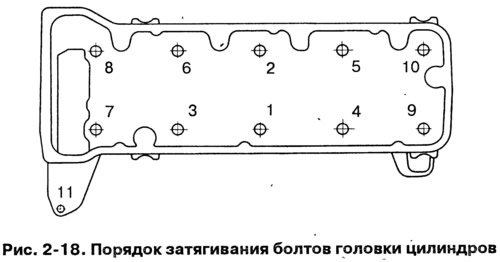
Tighten the cylinder head bolts in sequence (pic. 2-18). To ensure a secure seal and avoid tightening the bolts during vehicle maintenance, tighten the cylinder head bolts in four steps:
- 1 - tighten bolts 1-10 to 20 Nm (2 kgf·m);
- 2 - tighten bolts 1-10 to 69.4-85.7 Nm (7.1 -8.7 kgf·m), and bolt 11 - with a torque of 31.36-39.1 N·m (3.2-3.99 kgf·m);
- 3 - tighten bolts 1-10 by 90°;
- 4 - tighten bolts 1-10 again by 90°.
Warning: Cylinder head bolts may only be reused if the bolt shank has extended to no more than 120 mm. If the bolt is longer, replace it with a new one.
Warning: Before assembling the engine, pre-lubricate the threads and bolt heads by dipping them in engine oil. Then allow excess oil to drain, after holding the bolts for at least 30 minutes. Remove oil from the bolt holes in the cylinder block.
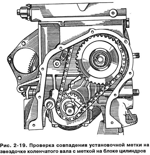
Turn the flywheel so that the mark on the crankshaft sprocket aligns with the mark on the cylinder block (pic. 2-19).
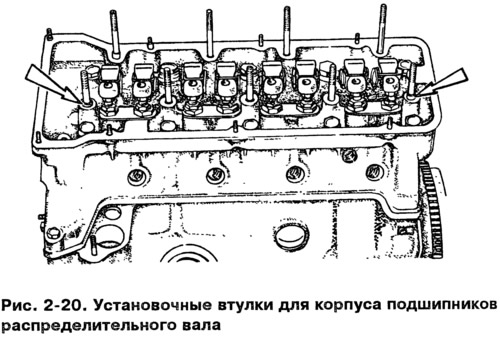
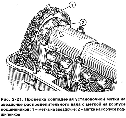
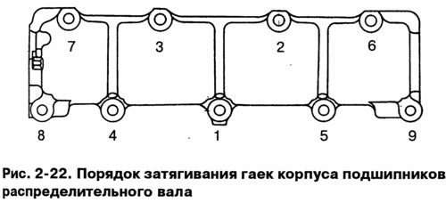
Check if the camshaft bearing housing dowels are in place (pic. 2-20). Install the sprocket on the camshaft assembled with the bearing housing and rotate the shaft so that the mark on the sprocket is against the mark on the bearing housing (pic. 2-21). Remove the sprocket and, without changing the position of the shaft, install the bearing housing on the cylinder head so that the mounting sleeves enter the bearing housing seats. Secure the bearing housing by tightening the nuts in the sequence shown in fig. 2-22.
Install the chain guide on the cylinder head.
Install the camshaft drive chain, for which:
- put the chain on the camshaft sprocket and insert it into the drive cavity, installing the sprocket so that the mark on it matches the mark on the bearing housing (pic. 2-21). Do not overtighten the sprocket bolt;
- install the sprocket on the oil pump drive shaft, also without finally tightening the fastening bolt;
- install the chain tensioner shoe and tensioner without tightening the cap nut so that the tensioner spring can press the shoe; wrap the chain restrictor pin in the cylinder block;
- turn the crankshaft two turns in the direction of rotation, which will provide the desired chain tension; check the alignment of the marks on the sprockets with the marks on the cylinder block and on the bearing housing (pic. 2-19 and 2-21);
- if the marks match, then by blocking the flywheel with lock A.60330/R (pic. 2-10), finally tighten the sprocket bolts, chain tensioner cap nut and bend the sprocket bolt lock washers; if the marks do not match, then repeat the chain installation operation.
Adjust the clearance between the camshaft cams and the valve actuating levers.
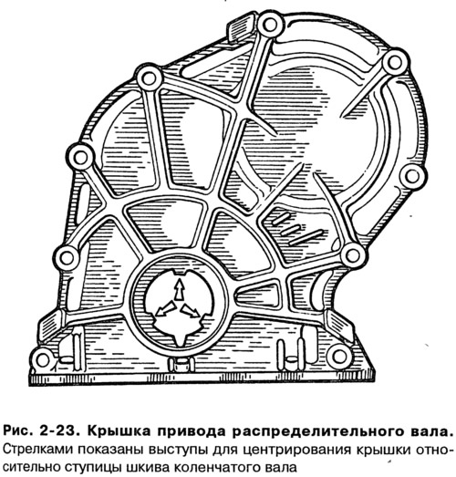
Install the camshaft cover (pic. 2-23) with a gasket and an oil seal on the cylinder block, without finally tightening the fastening bolts and nuts. Using mandrel 41.7853.4010, center the position of the cover relative to the end of the crankshaft and finally tighten the nuts and bolts of its fastening.
Install the alternator and pump drive pulley and secure with a nut.
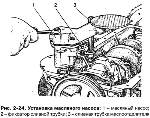
Install the oil filter with gasket by hand screwing it to the fitting on the cylinder block. Install the crankcase breather oil separator, breather cap and attach the oil separator drain tube retainer.
Install oil pump 1 (pic. 2-24) and oil sump with gasket.
Install the coolant pump, alternator bracket and alternator. Put the belt on the pulleys and adjust its tension.
Install the heater core inlet pipe and the cooling jacket outlet pipe on the cylinder head. Attach the heater core outlet pipe to the coolant pump and exhaust manifold.
Install control gauges.
Install the oil pump drive gear and the ignition distributor sensor, and then the ignition distributor sensor. Wrap the spark plugs, install the key 67.7812.9515 on them and tighten with a torque wrench.
Establish the fuel pump according to subsection instructions «Supply system».
Install the carburetor and attach the hoses to it. Close the carburetor from above with a technological plug.
Warning: Not allowed to mount (or tightening nuts) hot carburetor.
Install the cylinder head cover with gasket and fuel line bracket.
Install the air filter by attaching the hoses to the air filter housing, install the filter housing with gasket to the carburetor, then install the base plate and secure the housing with nuts. Install the filter element and secure the filter cover.
Connect the high voltage wires to the ignition distributor and to the spark plugs.
Pour engine oil into the engine through the opening on the cylinder head cover.
