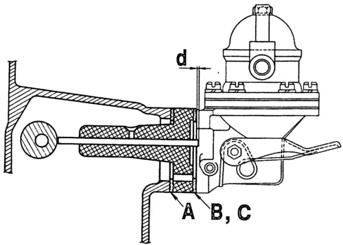
The pump installation diagram is shown in fig. 2-80. Install in the following order.

Pic. 2-80. Scheme for monitoring and adjusting the protrusion of the pusher of the pump drive:
A - gasket 0.27-0.33 mm thick; B - gasket 0.70-0.80 mm thick; C - gasket 1.1-1.3 mm thick; d - protrusion of the pusher.
Install the heat-insulating spacer on the cylinder block, placing gasket A between them, and place gasket B on the plane in contact with the pump. Using tool 67.7834.9506, measure distance d (the minimum amount that the pushrod protrudes, set by slowly turning the crankshaft). If the dimension d is in the range of 0.8-1.3 mm, then fix the pump on the engine. If d is less than 0.8 mm, replace gasket B with gasket A. If d is greater than 1.3 mm, replace gasket B with gasket C. Check dimension d again and mount the pump on the motor.
Between the cylinder block and the heat-insulating spacer, there must always be a gasket A.
