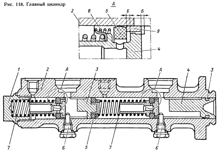
In the initial position of the pistons, the spacer rings 9 abut against the screws 6. At the same time, the sealing rings 5 move away from the end surface of the piston grooves and through the resulting gaps B, the working cavities of the cylinder are filled with liquid from the tank. When you press the pedal, the pusher moves the piston 4 forward (to the left). The spacer ring 9 ceases to put pressure on the sealing ring 5, and it, pressing against the end of the piston groove under the action of the spring 8, separates the reservoir cavity from the cylinder cavity. This ends the free travel of the piston, which is 3-5 mm on the brake pedahp further movement of the piston 4, the pressure in the cavity of the circuit of the brake mechanisms - the right front and left rear wheels increases and under its action the piston 3 of the drive of another circuit moves. With good circuits, the pressure in both working cavities of the cylinder will increase equally.
