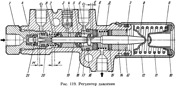
The pressure regulator has four chambers: A and D (pic. 119) are connected to the master cylinder, B - to the right, and C - to the left wheel cylinders of the rear brakes. In the initial position of the brake pedal, the piston head 14, under the force of the spring 11, is pressed from the seal 6 and abuts against the pusher 19, moving the valve 21 through it, which moves away from its seat 20. In this case, gaps M and E are formed. Through the formed gaps of the chamber A and D connected to chambers B and C.

When you press the pedal, the brake fluid through the gaps M and E and chambers B and C enters the wheel cylinders of the brake mechanisms. With an increase in fluid pressure, the force on the piston increases, tending to push it out of the housing. When the force from the fluid pressure exceeds the force from the spring 11, the piston begins to move out of the body, and after it the valve 21 and the pusher 19 move under the action of their spring (3,5±0,5) MPa gaps M and E are selected completely, and a further increase in pressure in chamber C will be due to the throttling of fluid between the piston collar 14 and seal 6, and in chamber B due to the displacement of sleeve 4 under the action of pressure in chamber C. After choosing gaps M and E, the pressure at the outlet of the regulator will increase to a lesser extent and is determined by the ratio of the areas of the shoulder and the piston rod.
In case of circuit failure «left front - right rear» O-rings 5, bushing 4 under the pressure of the liquid in chamber C will move towards the plug until clearance K is selected. The pressure in the rear brake will be regulated by the part of the pressure regulator, which includes piston 14 with seal 6, bushing 13 with retaining ring 7, spring 11 with stop 8 and ring 9. In this case, the operation of this part of the pressure regulator in the event of a failure of the named circuit will be the same as with a working system.
In case of circuit failure «right front - left rear» there is no pressure in chamber C. Due to the fluid pressure in chamber B, the pusher 19 and piston 14 are displaced, overcoming the force of the spring 11. Since the cross-sectional area of the pusher is less than the cross-sectional area of the piston 14, the gap M will be selected at a higher pressure than with a working system. The regulator will work as a pressure limiter with a pressure limit of 6-7 MPa.
