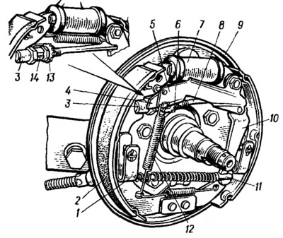
Pic. 121. Rear wheel brake: 1 - leaf spring; 2 - brake shoe; 3 - stop pads; 4 - plate; 5 - adjusting lever; 6 - adjusting nut; 7 - wheel cylinder; 8 expander pads; 9 - brake shield; 10 — the lever of a manual drive of pads; 11 - tip of the rear cable, 12 - spring; 13 - adjusting nut (for manual adjustment); 14 - adjusting nut lock.
Lever 10 (pic. 121) of the manual drive of the pads is pivotally connected by a bolt to the rib of the rear pad. Between the lever 10 and the edge of the front block there is an expansion bar 8 of adjustable length. It consists of the bar itself, the stop 3 of the shoe and the adjusting nut 13 of the expansion bar and thus adjust the gap between the shoes and the drum.
A device for automatic clearance adjustment is installed on VAZ-11113 vehicles. It is arranged as follows. The adjusting lever 5 of the automatic device, together with the lever 10 of the manual drive of the pads, is pivotally bolted to the rear brake shoe. Additionally, the adjusting lever 5 and the lever 10 of the manual drive of the pads are pivotally connected to each other by a pin. At the other end of the adjusting lever, a finger is fixed, which rests on the inclined surface of the plate 4, welded to the stop 3 of the block. In this position, the adjusting lever is engaged with the tooth of the adjusting nut 6.
When braking with a parking brake, the lever 10 of the manual drive of the pads rotates on the bolt. In this case, the force from the lever through the pin is transmitted to the adjusting lever 5, and its other end rises. In this case, the spring is stretched and the lever finger moves away from the plate 4. If the gap between the block and the drum exceeds the specified one, then the lever 5, rising, moves to the next tooth. When releasing the lever 5, due to the force of the spring 12, turns the adjusting nut 6, thus lengthening the expansion bar.
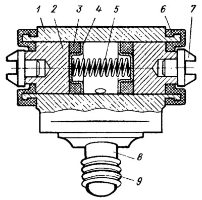
The wheel cylinder of the brake mechanism consists of a body 1 (pic. 122), in which two pistons 2 with seals 3 and a spacer spring are located. The cylinder cavity is sealed with covers. The brake mechanism drive is bled through fitting 8.

Pic. 122. Wheel cylinder: 1 - cylinder body; 2 - piston; 3 - sealant; 4 - spring cup; 5 - spring; 6 - protective cap of the cylinder; 7 - stop pads; 8 - fitting for pumping; 9 - fitting cap.
Parking brake system with a mechanical drive, acts on the brake mechanisms of the rear wheels. The parking brake drive consists of a lever 2 (pic. 123), adjusting rod 7, equalizer 8, cable 10, lever 10 (see fig. 121) manual drive of pads and expansion bar 8 of adjustable length.

Pic. 123. Parking brake drive: 1 - button for fixing the lever; 2 - parking brake lever; 3 - latch rod; 4 - latch; 5 - gear sector; 6 protective case; 7 - thrust; 8 - cable equalizer; 9 - adjusting nut; 10 - cable.
