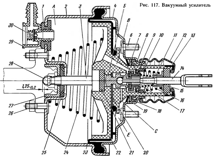
The amplifier is attached to the bracket plate of the clutch and brake pedals on four studs 6 (pic. 117) with nuts and the main cylinder - to the vacuum booster on two studs 26. Between the body 2 and cover 4, the outer belt of the rubber diaphragm 23 is clamped, which divides the booster into vacuum A and atmospheric E cavities. The vacuum cavity is connected to the engine intake pipe through a hose with a tip 29 and a valve 30. Inside the vacuum booster there is a plastic valve body 22, the shank of which, at the exit from the vacuum booster body, is sealed with a seal 18. It is installed in the socket of the booster body and is pressed against the flange of the socket with a distance ring 7, which is locked with a retaining ring 19. To protect the shank from contamination on the flanged part of the amplifier body and a corrugated protective cap 12 with a steel clip 13 is put on the shank of the valve body. A buffer 21, a piston 5 with a pusher 14, a rubber valve 9, springs 16 and 17 with support cups 8 to 11 and an air filter 15 are placed in the valve body 22. The thrust plate 20 enters the groove of the piston 5, the other end of which rests against the diaphragm belt 23, which prevents it from falling out. This plate fixes the piston assembly with the pusher 14 and the valve 9 in the housing 22. The rod 3 of the master cylinder piston drive rests against the buffer 21. At the outlet of the vacuum booster housing, the rod is crimped with a seal 25, which is pressed by the clip 27 to the housing seat 2, creating the necessary tightness of the booster housing. A bolt 28 is screwed into the end hole of the rod, which regulates the output of the rod from the amplifier housing (1,25-0,2 mm). The ball head of the pusher is crimped into the piston seat.
The rubber valve 9 is assembled on the pusher 14. The movable valve head, reinforced with a metal washer, is pressed by the spring 17 through the support cup 8 to the rear end of the piston 5 (at full disengagement). The body 22 has a seat for the movable valve head. The fixed shoulder of the valve 9 is pressed by the spring 16 through the support cup 10 to the inner wall of the valve body shank, creating a reliable seal. To clean the atmospheric air, a foam filter 15 is installed in the shank of the valve body. The valve body is constantly pressed by the spring 24 towards the cover 4. The cover and the amplifier body are connected to each other by inserting the protrusions of the cover into the cavity of the body and further turning the cover until its edges are wound under the protrusions of the body. The connector of the cover and the body of the amplifier is sealed with a shoulder of the diaphragm 23, sandwiched between them.
In the case of the amplifier, a plastic tip 29 of the hose is attached through a rubber flange 1, into which valve 30 is mounted. It prevents the hot mixture from entering the vacuum cavity A of the amplifier. When the system is disengaged and the brake pedal is in its original position, the pusher 14, together with the valve body 22 and the stem 3, are pressed by the spring 24 to the rearmost position - a gap is formed between the valve head 9 and the valve body seat, as the piston 5 presses the valve from the seat. The vacuum cavity A through channel B, the gap between the seat and the valve and further through channel C communicates with the atmospheric cavity E. Therefore, when the engine is running, the vacuum from the engine intake pipe through valve 30 is transmitted to cavity A and through channels and gaps to cavity E.
When the brake pedal is pressed, the pusher 14 moves the piston 5. Following the piston, the valve 9 moves under the action of the spring 16 until it stops against the seat of the valve body. When the saddle overlaps, cavities A and E are separated. With further movement of the piston 5 between them and the shoulder of the valve 9, a gap is formed through which the cavity E is connected to the atmosphere. Outside air enters cavity E through filter 15, the gap between the pusher and the valve, and then through channel C. Atmospheric air creates pressure on diaphragm 23. Due to the pressure difference in cavities A and E, as well as the force on the brake pedal, the valve body moves together with rod 3, which, in turn, acts on the piston of the brake master cylinder. The force acting on the valve body depends on the degree of vacuum in the intake pipe and on the force on the pedal.
