- keys "on 7", "for 8", "at 11" And "at 13"
- set of drills Zh1.1-1.5 mm
- copper wire Zh0.2-0.25 mm
- screwdrivers
- pliers with long thin jaws
Remove the carburetor from the car (see subsection 10.10.7.).
The need for complete disassembly of the carburetor arises in cases where flushing and adjustment with partial disassembly do not lead to the restoration of its performance.
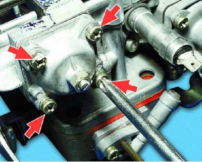
1. Loosen the four screws securing the starter cover.
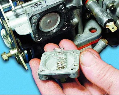
2. Remove the cover along with the spring.
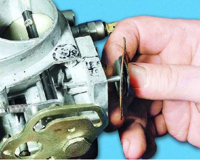
3. Carefully remove the actuator diaphragm with stem.
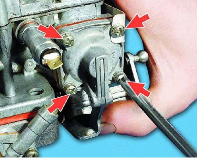
4. Remove the four screws securing the accelerator pump cover.
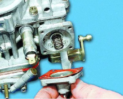
5. Remove the cover with the drive lever and the accelerator pump diaphragm.
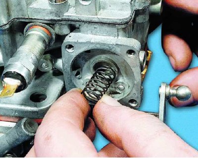
6. Take out the spring.
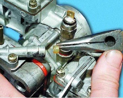
7. Remove the plastic plug from the adjusting screw housing.
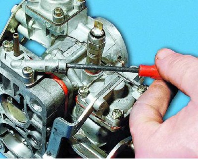
8. Loosen the adjusting screw and...
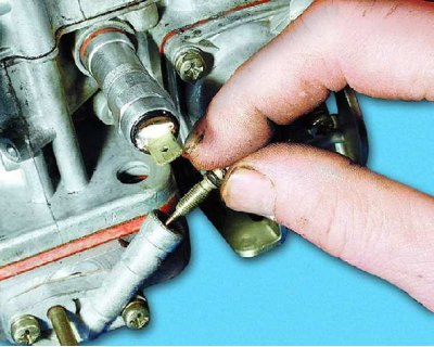
9.... take it out of the case.
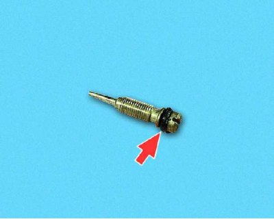
10. Replace a torn or loose sealing ring on the adjusting screw.
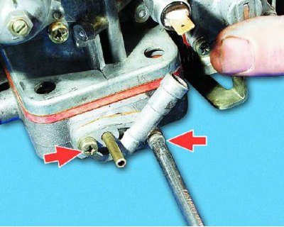
11. Loosen the two screws securing the adjusting screw housing.
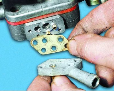
12. Remove the housing and seal. Replace a torn or severely compressed gasket.
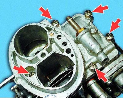
13. Loosen the five screws securing the carburetor cover.
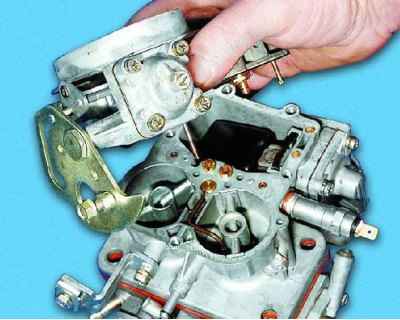
14. Remove the carburetor cover.
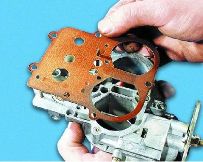
15. Remove the cover gasket. Replace a torn or severely compressed gasket.
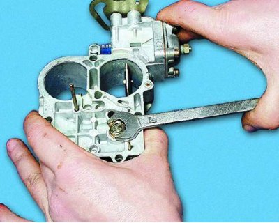
16. Unscrew the fuel valve from the cap.
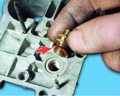
17. Inspect the valve's copper sealing ring. Replace heavily compressed ring.
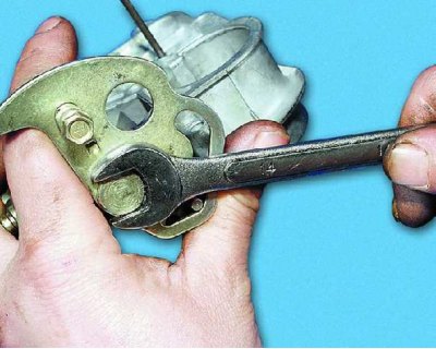
18. If necessary, turn off the axis of the air damper control lever.
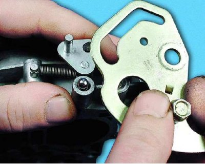
19. Remove the choke control lever, lever lock ball and spring. Do this carefully: the spring-loaded ball can get lost. Replace broken spring.
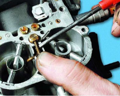
20. Carefully pry with a screwdriver...
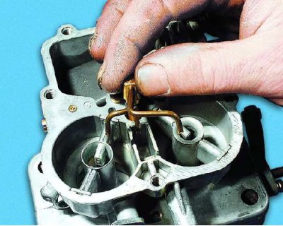
21.... remove the body of the accelerator pump sprayers.
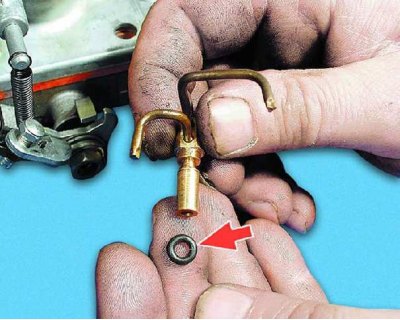
22. Replace torn or loose sealing ring.
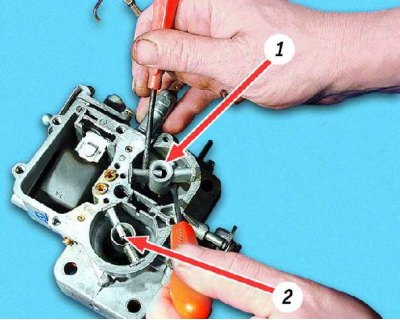
23. If necessary, using two screwdrivers, remove the atomizer 1 from the first chamber and the atomizer 2 from the second chamber.
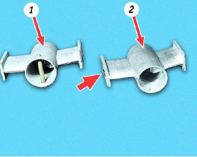
24. Please note: the atomizer 1 of the first chamber, unlike the atomizer 2 of the second chamber, has a transverse pin, and spring clips are inserted into the ends of the atomizer legs. Don't lose them.
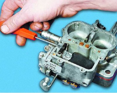
25. Using a screwdriver, remove the float pin.
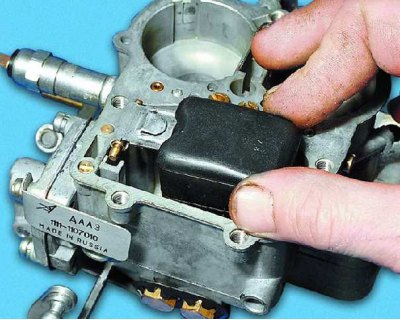
26. Remove the float together with the axle from the carburetor body.
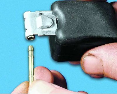
27. Remove the float shaft from the bracket.
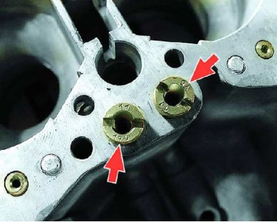
28. Remove the main air jets from the carburetor body. Please note: jets have different markings. Don't mix them up.
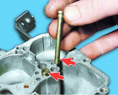
29. Remove the jets with emulsion tubes from the body.
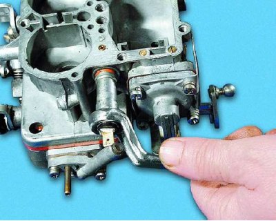
30. Unscrew the EPHX solenoid valve.
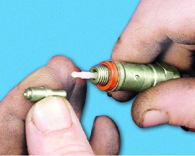
31. Remove the idle fuel jet from the valve.
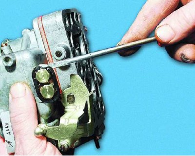
32. Using a screwdriver, remove the lock plate of the main fuel jet plugs.
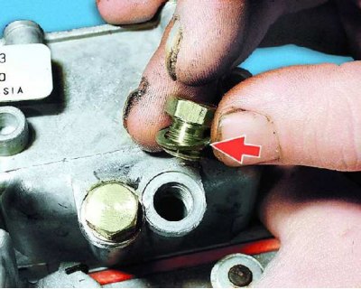
33. Remove plugs. Please note: copper sealing washers are installed under the plugs. Replace heavily compressed washers.
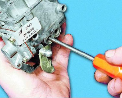
34. Unscrew the main fuel jets from the carburetor body.
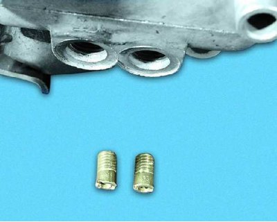
35. Pay attention to the marking of the jets. For carburetors mod. 11113 it is different. Don't mix up jets.
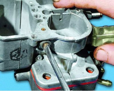
36. Turn out the holder of the fuel jet of the transitional system of the second chamber.
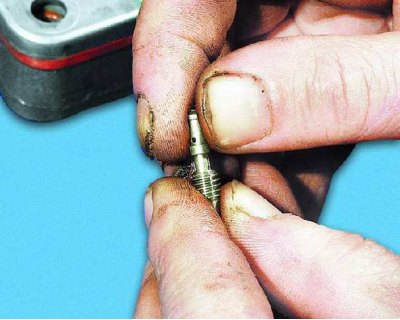
37. Remove the fuel jet of the transition system of the second chamber from the holder.
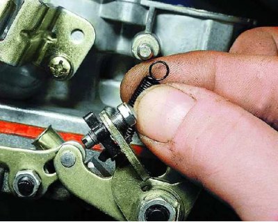
38. Remove the second chamber intermediate throttle lever return spring.
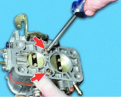
39. Remove the two screws securing the throttle body to the carburetor body.
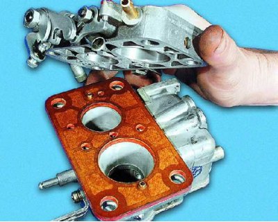
40. Separate the carburetor and throttle bodies.
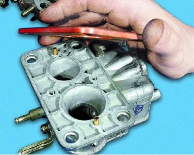
41. Remove the thermal pad.
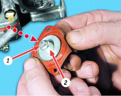
42. The diaphragm of the accelerating pump must not have tears or delaminations. The pusher 1 of the diaphragm support cup must move without jamming in the cup body 2 and clearly return to its original position by the damping spring.
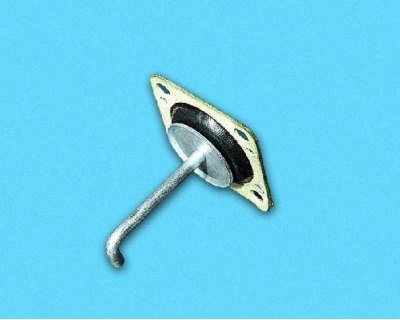
43. The diaphragm of the starting device should not have tears and delaminations. The stem must be securely fixed in the diaphragm cup, and the cardboard seal must not be torn or severely compressed.
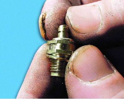
44. Check fuel valve. Its needle should move easily in the saddle and should not have much radial play. The ball of the needle should move easily in its seat and be clearly returned to its original position by the damping spring.
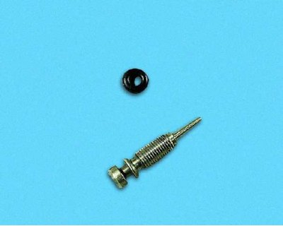
45. Inspect the adjusting screw and its o-ring. The taper shank of the screw and the threads must not be damaged. The sealing ring must not be torn or heavily compressed.
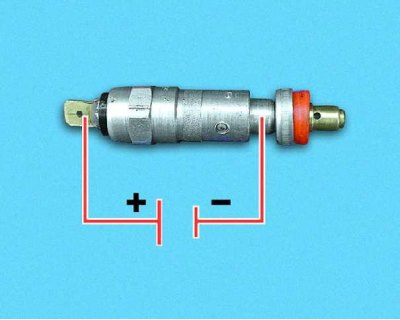
46. Install the idle fuel jet to the solenoid valve. Check the solenoid valve by connecting it as shown. When voltage is applied, its core should be pulled into the winding with a click, and when turned off, it should completely return to its original position.
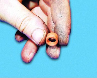
47. The rubber sealing ring of the solenoid valve must not be torn or strongly compressed.
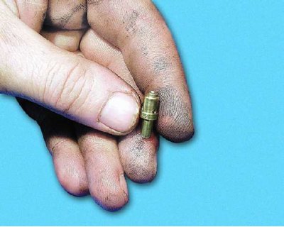
48. Pay attention to the marking of the idle fuel jet and install the same new jet when replacing. The walls of the jet housing must not be deformed from overtightening.
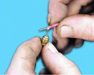
49. If necessary, clean the jet with thin copper wire or fishing line.
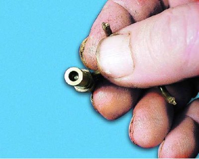
50. Check the accelerator pump injector assembly. When shaking in your hand, the check valve ball located inside the block body should move with clicks.
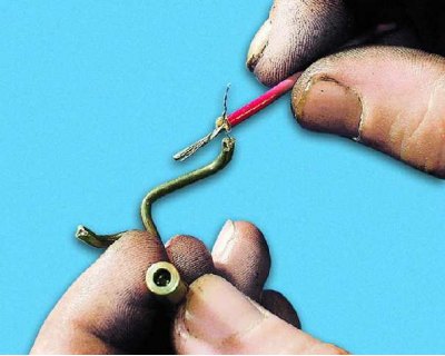
51. If necessary, clean the nozzle holes with fine copper wire.
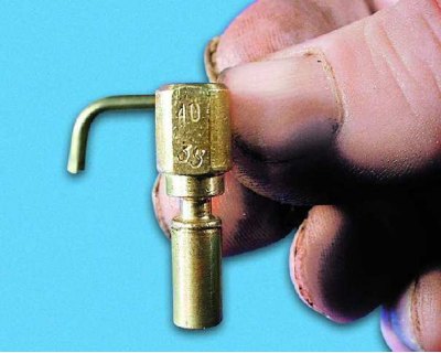
52. Pay attention to the marking of the atomizer block and install the same one when replacing with a new one.
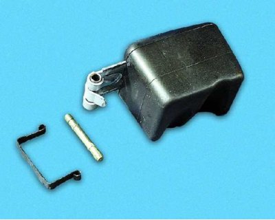
53. Inspect the float and its attachment details. If the float is leaking or its bracket is damaged, replace the float with a new one, checking its mass, which should not exceed 8.01 g. Clean the oxidized float axis with fine emery cloth. Replace severely deformed axle lock.
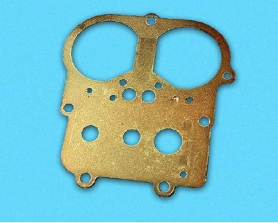
54. Replace a torn or severely crimped carburetor cover gasket.
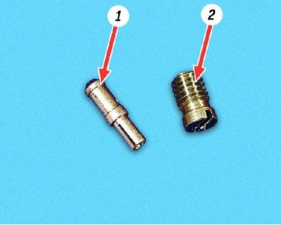
55. The walls and holes of the fuel jet 1 of the transition system must not be deformed by excessive tightening. The thread and slot of holder 2 must not be damaged.
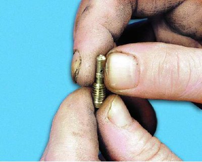
56. Pay attention to the marking of the jet and, if necessary, replace it with the same one.
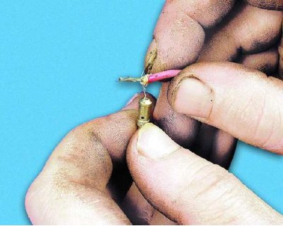
57. Clean the jet with thin copper wire or fishing line.
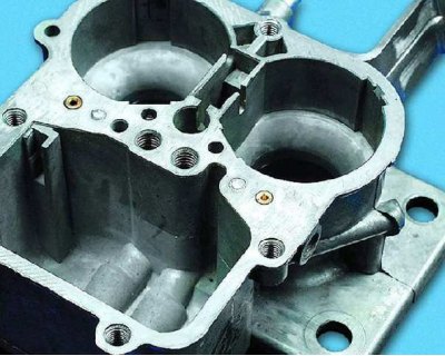
58. Inspect the mating surfaces of the carburetor body...
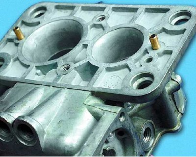
59....throttle bodies and...
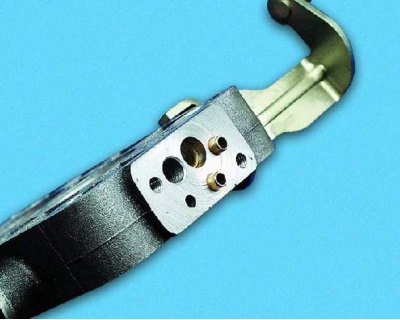
60.... flange of the block of the adjusting screw of idling. They should not have chips and nicks.
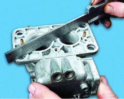
61. Check mating surfaces for warpage from overtightening fasteners. To do this, attach a caliper shank or a metal ruler to the surface in several directions. The gap between the surface and the ruler should be no more than 0.02 mm. If necessary, straighten the surface with light hammer blows through a soft metal mandrel and rub in with fine-grained emery cloth.
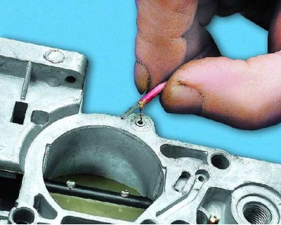
62. Clean the damping jet of the vacuum supply channel to the diaphragm mechanism of the starting device in the carburetor cover with a thin copper wire or fishing line...
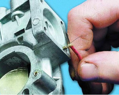
63....the hole in the adapter sleeve of this channel...
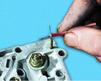
64.... fuel pickup jet of the inertial economizer...
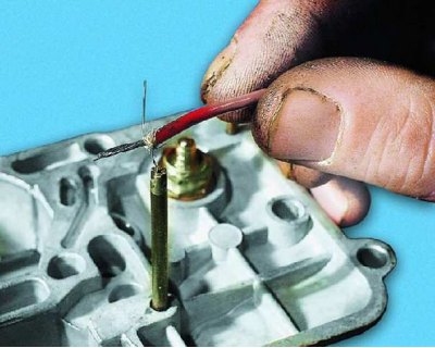
65....econostat fuel pickup jet...
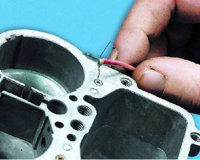
66.... air jet of the transition system of the second chamber in the carburetor body and...
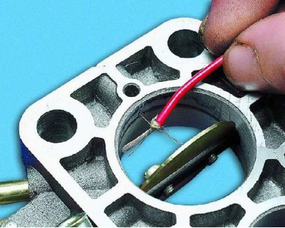
67.... the outlet of the transition system of the second chamber in the throttle body.
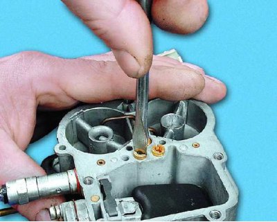
68. Assemble the carburetor in the reverse order of disassembly. At the same time, in order not to damage the jets and not disturb their calibration when installed in the threaded holes of the carburetor body, do not apply excessive force when tightening and use only perfectly serviceable, precisely sized screwdrivers.
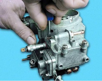
69. Tighten the screws securing the carburetor cover, as well as the starter and accelerator pump covers tightly, but without excessive force. Do not replace stock spring lock washers ("growers") more rigid, damaging the soft surfaces of the carburetor body parts.
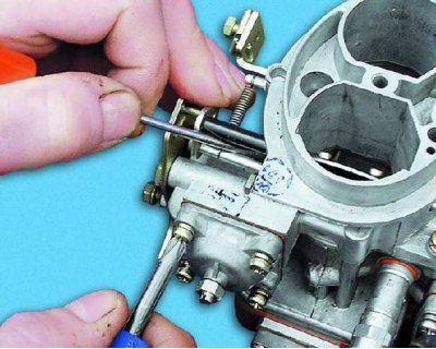
70. When assembling the starting device and the accelerator pump, install their covers without tightening the fastening screws. Fully cross-tighten the screws, having previously sunk the diaphragm rod of the trigger to the stop with a screwdriver...
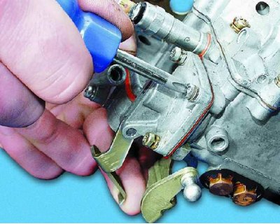
71.... and pulling the accelerator pump drive lever all the way.
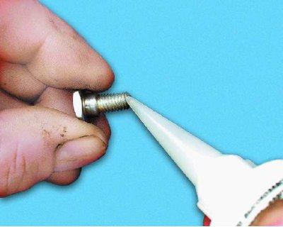
72. Before installing the axis of the air damper control lever, to prevent self-loosening, lubricate its end face and 1–1.5 extreme threads of the thread with UG-9 adhesive-sealant, Loktite 243 or similar.
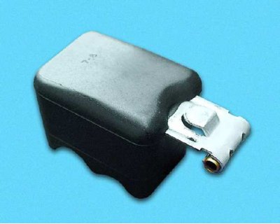
73. If you use a float from a repair kit when assembling, be sure to check its mass. It should be no more than 8.01 g.
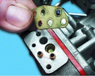
74. Install gaskets and diaphragms only "dry", without the use of any sealants. The sealant will inevitably get into the channels of the carburetor and disable it.
